JBT Review Mat Flashcards
Minimum DFU and Trap Diameter for:
Water Closet
Private - Re - Kola
Public - Go - Kola
Minimum DFU and Trap Diameter for:
Lavatory
Single - to moon
Set - no move
Minimum DFU and Trap Diameter for:
Bidet
no move
Minimum DFU and Trap Diameter for:
Urinal
Wall Mounted - go lice
Stall - no lice
Trap arm - me lice
Pedestal - go kola
Blowout - go kola
Washdown/Siphon Jet - no lice
Washout (50mm Waste) - no move
Minimum DFU and Trap Diameter for:
Cloth Washers
no Lice
Minimum DFU and Trap Diameter for:
Bathtub
no move
Minimum DFU and Trap Diameter for:
Dental Unit/Cupsidors
to moon
Minimum DFU and Trap Diameter for:
Mobile Home
go kola
Minimum DFU and Trap Diameter for:
Sinks
Kitchen Sink - no move
Bar Sink (Commercial)(50mm waste) - no move
Bar Sink (Private) - to move
Sink (Commercial,Industrial, institutional) (50mm waste) - me move
Sink Clinic - go kola
Service Sink (Slop Sink) - me lice
Minimum DFU and Trap Diameter for:
Drinking Fountain
to moon
Minimum DFU and Trap Diameter for:
Shower Bath
Single - no lice
Gang - 1 unit per head
Minimum DFU and Trap Diameter for:
Floor Drains
no lice
Minimum DFU and Trap Diameter for:
Receptors
Minimum DFU and Trap Diameter for:
Interceptors
Grease/Oil - me lice
Sand/Autowash - go kola
Minimum DFU and Trap Diameter for:
Laundry Tub
No move
Label and Illustrate Table 1 @ Yellow
Size of Roof Leader and Gutter
Label and Illustrate Table 2 @ Yellow
Size of Storm Drain
Label and Illustrate Table 3 @ Violet
Oukum Per Joint
Label and Illustrate Table 4 @ Violet
Lead Per Joint
Label and Illustrate Table 0.00 @ Yellow
Consonant System`
Label and Illustrate Table 5 @ Green
Size of Sanitary Drain
Label and Illustrate Table 6 @ Blue
Vent Sizing
Label and Illustrate Table 7 @ Blue
Table for Air Gap
Label and Illustrate Table 8 @ Blue
Engagement Length for Plastic PIpe
Label and Illustrate Table 9 @ Blue
Soil and Waste Pipe Sizing
Illustrate Provision for “Hangers and Support for Lead Pipe”
See answer @ Sketch Book
Illustrate Provision for Air Gap
Illustrate Provision for Cast Iron Soil Pipe (Supports for Vertical and Horizontal)
Illustrate Provision for prohibited fittings for Cast Iron Pipe
A cylindrical conduit or conductor conforming to the particular dimensions commonly known as (pipe size) and is denoted by its Interior diameter or (ID)
Pipe
Used to join two or more pipes together or to change their directions
Fitting
This is the pipe that conveys waste from the building to an approved point of disposal.
Types of Drainage Pipes:
Waste Pipe
Soil Pipe
Storm Pipe
Vent Pipe
A pipe which conveys only waste water or liquir waste, free of fecal matter.
Waste Pipe
Any pipe which conveys the discharge of water closet, urinal or fixtures having similar functions, with or without the discharge from other fixtures to the building drain or building sewer.
Soil Pipe
A pipe which conveys the rainwater from the roof gutter to the downspout and discharges it to the building storm drain.
Storm Pipe
A pipe or opening used for ensuring the circulation of air in a plumbing system and for relieving the negative pressure exerted on trap seals.
Vent Pipe
Is a pipe that runs horizontally.
Branch
Is a pipe that runs vertically.
Stack
This kind of pipe is made of fibrous carcinogenic silicate mineral combined with Portland Cement. This pipe is remarkably superior for embedment in concrete structure for having the same material properties. Used as soil pipe, waste pipe, vent and downspout.
Asbestos Cement Pipe
Two types of Asbestos cement:
Pressure AC pipe
Non-pressure AC pipe
Is a type of AC pipe used for sewer mains, industrial effluent and process piping. Working pressure ranges at 100, 150, and 200 psi.
Pressure AC Pipe
Is a type of AC pipe used for sewer castings for electric cables and storm drains.
Non-pressure AC pipe
Available diameter in an AC pipe:
3” - 36”
Available Length in AC pipe:
3.00m and 4.00m for 3,4, 6,8”
Available grades for AC pipe and their means of joinery:
1500, 2400, 3000, 4000, 5000lb/ft and rubber gasket or cement joint
Enumerate and Illustrate Asbestos Pipe Fittings: (12)
Tee, Cross tee, Sanitary Tee, Sanitary Cross Tee, Sanitary Wye, Double Wye, Running Trap, P-trap, 30d Bend, 45d bend, 60d Bend, 75d Bend,
Made from an alloy of iron, carbon and silicon, with the controlled amounts of manganese, sulfur and phosphorous. This is primarily used for sanitary drain, waste and storm systems.
Cast Iron Soil Pipe (CISP)
Classifications of Cast Iron Soil PIpe:
Class A/ Extra HEavy Duty (XV)
Class B/ Service Weight (SV)
Class of CISP - is often used for underground installations.
Class A/XV
Class of CISP - is used for general building installations.
Class B/ SV Type
Types of CISP: (3)
Single Hub, Double Hub, Hubless Pipe
CISP - is constructed with one hub and one spigot end and used in the installation of plumbing in its full length.
Single Hub
CISP - is contructed with a hub on each end so it may be cut into two pieces when a short piece of pipe is needed.
Double Hub
CISP - Are cast iron soil pipe with plain ends connected together with bolted stainless steel bands and neoprene gaskets.
Hubless pipe.
Laying Length for CISP:
5’ and 10’
Available diameter for CISP:
2, 3, 4, 5, 6, 8, 10, 12, 15”; with corresponding Engagament Length of 62mm, 68, 75,75, 75
Hydrostatic test for CISP types of pipe.
50 psi for SV
100 psi for XV
Types of Joints for CISP: (3)
Lead and Oakum (Calking)
Neoprene Compression Gasket
Stainless Steel Coupling
Hemp treated with pitch to make it moisture proof and resistant to the elements contained in the waste.
Oakum
Is plugging an opening with oakum, lead or other materials that are pounded into the annular opening.
Calking
That portion of the pipe which, for a short distance, is sufficiently enlarged to receive the end of another pipe of the same diameter for the purpose of making a caulked or push-on joint.
Hub/Bell
the end of the pipe that fits into a bell.
Spigot
National Plumbing Code of the Philippines
Section 311 - Prohibited Fittings and Practices:
No ______ fitting for lead-caulked joint in vertical position. No ______(5 fittings) shall be used as a drainage fitting, except that a double hub sanitary tapped tee may be used on vertical lines as a fixture connection. (Approved stainless bands with neoprene gaskets for jointing of hubless cast iron soil pipes are acceptable for use.)
Double Hub;
Single or double tee branch, single or double tapped tee branch, side inlet quarter bend, running thread, band or saddle
National Plumbing Code of the Philippines:
Section 315 - Hangers and Supports:
Vertical Pipe
Cast Iron Soil Pipe - Bell and Spigot and Hubless pipe shall be supported at _____.
every storey or closer
National Plumbing Code of the Philippines:
Section 315 - Hangers and Supports
@ Horizontal Pipie
Cast Iron Soil Pipe - where joints occur, suspended cast iron soil pipe shall be supported at not more than ______ intervals; except that pipe exceeding 1.50 meters length may be supported at not more than _____ intervals. Supports shall be adequate to maintain alignment and to prevent sagging and shall be placeed within ______ of the hub or joint. __________ joints must be supported at least at every other joint except that when developed lenth between supports exceeds ______, they shall be provided at each joint. Support shall also be provided at each horizontal branch connection, placed on or immediately adjacent to the coupling.
1.50 meters
3 meters
0.45 meters
Hubless or compression gasket
1.2 meters
Is cast in metal molds and compacted by tamping or spinning the molds.
Concrete Pipe
Types of Concrete Pipe:(2)
Non-Reinforced Concrete Pipe
Reinforced Concrete Pipe (RCP)
Is used for drainage, sewer lines and for gravity-flow water supply lines of the joints are carefully made. Diameters of the pipe are available in range rom 4” to 36”
Non-Reinforced Concrete Pipe
Is made by the addition of steel wire or steel bars and is primarily used for sewage and storm drainage. Diameters of the are available in range from 12” - 144”
Reinforced Concrete Pipe (RCP)
Available pipe diameter for Non-RCP
4” - 36”
Available pipe diameter for RCP
12” - 144”
Is extruded from a suitable grade of shale or clay and fired in kilns producing an extremely hard and dense corrosion resistant material. It is generally used for underground public sewer, house sewers, drainage (sanitary and storm) systems and for industrial wastes such as acids.
It is suitable for most gravity flow systems and is not intended for pressure service. It is brittle and cracks when laid on unstable ground or lose.
Vitrified Clay Pipe
Diameter for Vitrified Clay Pipe
4” - 42”
Grades for Vitrified Clay Pipe
Standard, extra strength, and perforated
Joinery for Vitrified Clay Pipe:
Cement Joint and Pre-fabricated Compression Seals
Enumerate and Illustrate Fittings for Vitrified Clay Pipe (11)
Short Curve, Tee branch, Y-branch, square L, slant, cut L, Cut Curve, running trap, offset, reducer, increaser.
Joinery for Concrete Pipe
Cement Joint
Is the cheapest among the sewer pipes. It is sometimes recommeded for house sewer and for septic tank installation. This type of pipe is light in weight, slightly flexible which could take slight soil movement without danger of cracking or pulling out from its joints. However, excessive hot water of chemical flow may soften or damge the pipe.
Bituminous Fiber Sewer Pipe
One of the oldest plumbing materials used by the Egyptians, Greeks and the Roman builders as soil and waste pipe. It is highly resistant to acid and is suitable for underground installation. But because this is poisonous and injurious to human health, it is never used to convey water for human consumtion.
Lead Pipe
How to distinguish pipe material for
Copper
Lead
Galvanized
Plastic
Is made out from mild steel, drawn through a die and welded, cast into 6.00 meters long. This type of pipe is easily corroded by alkaline and acid water. The carbonic acid in water attacks the zicn coating and ultimately the steel itself. It is subject to deposits of salt and lime that gradually accumulate and finally choke the flow of water. It deteriorate faster when used as hot water supply line.
Galvanized Steel Pipe.
Is better in quality that Galvanized steel pipe for plumbing installation. Tests showed that wrought iron pipe is more resistant to acid water than the steel pipe.
Galvanized Wrought Iron Pipe
Is one of the most expensive types of pipe. This pipe is made of an alloy or zinc and copper mixed at 15% and 85% proportion respectively. Because of its smooth interior surface and high resistance to acid, brass pipe become superior material for waste and water supply installations. Brass pipe fittings are of the recessed type similar in design with galvanized steel pipe.
Brass Pipe
Is a durable and extremely corrosive resistant material. It is easy to install compared with other types of pipe. It is classified into three types depending upon its wall thickness.
Copper Pipe
Type of Copper: Is the heaviest. It is suitable for underground installation.
K Type
Type of Copper: Is lighter than L ty[e available in both the rigid and flexible form. It is commonly used in residential water supply line and for radiant heating installations.
L Type
Type of Copper: Is the thinnest and available only in a rigid form. This type of copper pipe is specially designed for small water supply lines and for radiant heating installations.
M type
National Plumbing Code of the Philippines:
Use of Copper Tubing
Copper tube shall not be used for piping carrying _____ as defined in secion 811 of the National Plumbing Code of the Philippines.
Chemical or Industrial Wastes
National Plumbing Code of the Philippines
Use of Copper Tubing
Copper tube for water supply piping shall have a weight of not less than ____.
Exception: Type M copper tubing may be used for water piping when piping is ______ or undergournd outside of structures with _______.
above ground inside or atop a building; outside protective coating
National PLumbing Code of the Philippines:
Use of COpper Tubing
In addition to the required incised marking, all hard drawin copper tubing shall be marked by means of a continous and indelibly colored stripe at least ______ in width, as follows:
Type K:
Type L:
Type M:
Type DWV:
6.4mm in width
Green;
Blue;
Red;
Yellow
____ Is available in compositions designed for various application including drain, waste and vent (DWV). It was introduced in the Philippines at the early part of 1970, although this type of material was developed in ____ in mi-year of 1935.
Plastic Pipes; Germany
Type of Plastic Pipe that has the property of being permanenty rigid. Epoxy and fiber glass are example.
Thermoset Plastic
Type of plastic pipe that is a material having the property of softening when heated and hardening when cooled.
Thermo Plastic
Thermoset Curing Process:
Thermoset Plastics contain _____ that cross-link together during the curing processs to form an “irrevesible chemical bond. The cross-linking process eliminates the risk of the product remelting when heat is applied, making thermosets ideal for high-heat application such as electronics and appliances.
Polymer
Thermoset plastics significantly improve the material’s mechanical properties, providing enhances _____, ____ and ____. Thermoset plastics are often used for sealed products due to their resistance to deformation.
Chemical Resistance, Heat Resistance, Sturctural Integrity
Thermoplastics pellets ____ when heated and become more fluid as additional heat is applied. The curing process is completely reversible as no chemical bonding takes place. This characteristic allows thermoplastic to be _____ and ____ without negatively affecting the material’s physical properties.
Soften;
Remolded and Recycled
There are multiple thermoplastic resins that offer various performance benefits, but most materials commonly offer ____, _____ and ______. Depending on the resin, thermoplastics can serve low-stress applications such as plastic bags or high-stress mechanical parts.
High Strength, Shrink-Resistance, Easy Bendability
Types of Plastoc Pipes for Drainage System:
_____ is used as drainage and sewer pipe for housing complex, playground, golf course, industrial farm and stock farm. It is sufficiently flexible to follow ground contours of snake arount obstacles.
Polyethly (PE) or High Density Polyethylene (HDPE)
Available Diameter for HDPE Spiral Pipe
4” - 36”
Joinery for HDPE Spiral Pipe:
Screw Type Couplings
HDPE Pipe Fittings (10)
Coupling; 90d bend; 45d bend; end cap; tee; tee reducer; cross tee; cross tee reducer; wye; double wye reducer
is a thermoplatic type which is composed of molecules of polymers. Each molecule is a long chain made of carbon, hydrogen and other atoms which are melted down and molded.
Polyvinyl Chloride (PVC)
Types of PVC pipes used for Drainage:
- is designed for above and underground sanitary piping system. It is ideal for drain, waste and vent (DWV) installation.
uPVC Sanitary Pipes
Types of PVC pipes used for Drainage:
can be used for main sewer system and other underground waste piping system which requires big diameter pipes.
uPVC Sewer Pipe
uPVC is also commonly known as _____. It is called this because it is hard and does not flex.
Rigid PVC
Substance added to plastics to increase their flexibility, transparency, durability, and longevity.
phthalates or BPA
A short piece of pipe, threaded on the outside (male threads) at both ends, used to joint coupling or other fittings,
NIpple
Short nipple is below ____ in length. Also known as ___
75mm; shoulder nipple
Long nipple is over ____ in length.
75mm
Type of nipple where threading meet
CLose nipple
A short internally threaded (female thread) at both ends and used to connect two pipes in straight line,
Coupling
a pipe fitting having a bend and makes an angle of 90 or 45 degrees between adjacent pipes for a change in drection. It is also known as ell or straight elbow.
Elbow
Joint two pipes of different diameters at right angle of each other. When specifying reducer fittings, the _____ is stated first, followed by the smaller diameter. Draw its symbol
Reducing Elbow
An elbow fitting having a 45 or 90 degree bend with an inside thread on one end and outside thread on the other.
Street El, Service El/ Stree el
a t-shaped pipe fitting that joints 3 or 4 pipes at perpendicular directions.
Tee
Water supply pipe, which extends vertically to one full story or more to convey water into pipe branches or plumbing fixtures.
Riser
a pipe coupling with inside threads, having one end with a smaller diameter than the other and used for connecting pipes of different size. Both openings have the same center line.
Illustrate Symbol
Reducer
a pipe fitting which is threaded on both the inside and the outside and used to reduce the size of the pipe opening to rreceive a pipe of fitting of a different size.
Illustrate symbol
Bushing
a pipe fitting used to close an opening in a fitting. Illustrate symbol
Plug
A pipe fitting used to close the end of a pipe.
Cap
a three piece pipe fitting used to connect the ends of two pipes, neither of which can be turned. It is also used on pipes that are to be taken down occasionally.
Label its parts and illustrate symbol
Union
Threaded Piece, Center Piece/ Collar, Shoulder Piece
a ring shaped plate screwed on the end of a pipe and provide with holes for bolts, to allow joining the pipe to a similarly equipped adjoining pipe, The resulting joint is a flanged joint.
Flange
Are used to control the flow of water throughout the supply system. The proper location of valves simplifies repairs to the system, fixtures, or equipment being served.
Valves
There are usually valve at: (3)
Pipes in individual fixture or equipement
Risers
Branch
A valve in which the flow of water is cut off by means of a circular disk fitted against machine smoothed faces, at right angles to the direction of flow. The disk is raised or lowered by means of a threaded stem connected to the handle of the valve. The opening in the valves is usually as large as the full bore of the pipe,
Gate Valve
A valve in which the flow of fluid is cut off by means of a circular disc that fits over and against the horizontal valve seat. The movement of the plane of disc parallel to the normal direction of the flow of water through the orifice resulting to a tortuous passage which offers a high pressure loss.
Globe Valve
Type of globe valve that has a wide bearing surface producing good resistance to the cutting effects of scale, dirt and other kind of foreign matter found inside the pipe.
Plug type disk Valve
A type of globe valve that has a pressure tight bearing between the disc and the seat recommended for cold water supply and temperature service.
Conventional Disc Valve
A type of globe valve that is used for various types of service on oil, gasoline, steam, and hot or cold water.
Composition Disc Valve
Have a disc that is equal in size to the inside diameter of the pipe, This disc is attached to a level handle that rotates the disc, which adjust the flow of water. The main drawback to this type of valve is that the control disc is always present within the flow of water (even when fully open) so there will always be a pressure drop when using them. Its use allow for fairly precise control of flow. They typically rely on a gasket to provide a full seal, which can become a maintenance issue.
Butterfly Valve
A diaphragm valve is similar to a gate valve in that there is a wheel or know that move an element in the valve fitting, which limits the flow of water. In a diaphragm valve, the element is a diaphragm that settles down over a saddle, thus stopping water flow. The diaphragm below is a weir-type diaphragm valve, where water passes over a weir. There is also a straight-type diaphragm valve, which doesnt force water over a weir.
Diaphragm Valve
A valve that automatically closes to prevent the flow of liquid or gas in a reverse direction.
Check Valve
Three types of Check Valve
Lift Check Valve
Swing Check Valve
Spring Loaded Valve
Operates in the same manner as the globe valve. It is available in similar range of disc and seat design. It is used in making 90 degree turn in a line to reduce the number of joints.
Angle Valve
Are made with a rotating sphere that has in it. In the open position, the hole in the sphere is in line with the pipe. When closed, the hold in the sphere is perpendicular to the pipe. THe level handle operates the valve, but also seves as an indicator for whether the valve is open or closed. When the lever is parallel to the pipe, the valve is open. Its use do not allow for precise flow control because they usually have positive stops (0, 45, 90 degrees), but they do provide a very good seal in the closed position.
Ball Valve
A valve located at the end of a water pipe through of which water can be drawn from or held within the pipe.
Faucet
is a valve mechanism which automatically releases a substance from a boiler, pressure vessel, or other system, when the pressure or temperature exceeds preset limits.
Pressure Relief valve
pressure balance valves are used to maintain a constant temperature of water in domestic showers or bathtubs. A diaphragm within the valve allows the operator to set mixing of hot and cold water, however in the event of a pressure drop of cold water (for instance , if a toilet neary is flushed), the diaphragm will shift to limit an excessive flow of hot water. Many jurisdictions require pressure balanced valves in domestic bathrooms and showers to prevent accidental scalding.
Pressure Balanced Valve
is used on cold water systems, heating systems, compressed air lines, and other pipe lines with excessive pressure.
Safety Valve
Is a device, which discharges a predetermined quantity of water into fixtures for flushing purposes and is actuated by direct water pressure.
Flushometer Valve
Illustrate and detail water supply connection from water main to water distributing pipes
is located at the lower end of the pump used to prevent loss of priming the pump. It is sometimes referred to as retention valve.
Foot Valve
Is inserted into the water main. It serves as a control of the water service, And also serve as a shut off, when the service is disconnected.
Corporation Stop
is installed between the curb and the sidewalk line accessible to cast iron stop box equipped with removable cover. It serves as control stop of the service between the curb and building. It shut off water supply in case the basement becomes flooded.
Curb Stop
A valve placed at the street side of the water meter and serves as a controlling device for the building installation.
Meter Stop
Are used in hydronic heating and colling systems to control the flow of water of steam. For instance, they may be provided in different rooms, different floors, or different dwelling units so that each space can have local control over the heating or cooling. In most applications, zone valve are electrically controlled and are connected to a thermostat so that automatic control is acieved.
Zone Valve
aLMOST ANY TYPE OF VALVE CAN BE LOCKED TO AVOID ACCIDENTAL OR INTENTIONAL OPENING OR CLOSING. hOWEVER, VALVE WITH LEVER-TYPE HANDLES ALLOW FOR MORE SECURE LOCKING CONTROL. LOcking valves provide aligning holes that a lock can be passed through to stop rotation of the handle. There are also locks designed to be attached to non-locking valves to prevent adjustment.
Locking Valve
a type of gate valve in which the valve stem and disk rise together when valve is open
Rising Stem Valve
a type of gate valve in which the valves stem doesnt rise together when valve is open.
Non-rising Stem Valve
The unobstructed vertical distance through the free atmosphere between the lowest opening from any pipe, plumbing fixture, appliance or appurtenance conveying waste to the flood level rim of the receptor.
Air Gap (drainage)
an unobstructed vertical distance through the free atmosphere between the lowest opening from any pipe or faucet conveying potable water to the floor level rim of any tank, lavatory or fixture.
Air Gap (water distribution)
A type of Back Flow Valve that consist of a body, a cheking member and an atmospheric opening.
(Illustrate its parts)
Atmospheric Vacuum Breaker (AVB)
A type of Back Flow valve consist of two independently acting internally or externally loaded check valve, four properly located test cocks with connectors and two isolation gate valves.
Double Check Valve Backflow Prevention Assembly (DC)
A type of Back Flow valve consist of a loaded air inlet, valve, an internally loadedcheck valve, two properly located test cocls and two isolation gate valves.
Pressure Vacuum Breaker Backflow Prevention Assembly (PVB)
A type of Back Flow valve consists of two independently acting internally loaded check valves, a different pressure relief valve, four properly located test cocks and two isolation gate valves.
Reduced Pressure Principles Backflow Prevention Assembly (RPP)
are approved type installed receptacles, devices or appliances supplied with water or receive liquid or liquid borne wastes and discharge such wastes into drainage system to which they may be directly or indirectly connected. Industrial or commercial tanks, vats and similar processing equipment are not plumbing fixtures, but may connected to or discharged into approved traps or pllumbing fixtures as provided in the National Plumbing Code of the Philippines.
Plumbing Fixtures
a manufactured device or a prefabricated assembly or an on the job assembly of components parts, and serves as adjunct to the basic piping system and plumbing fixtures. An appurtenance demands no additional water supply nor does it add any discharge load to a fixture or the drainage system. It performs some useful functions in the operation, maintenance, servicing, economy or safety of the plumbing system.
Plumbing Appurtenance
any one of a special class of device or equipment intended to perform a special plumbing fuction. Its operation and/or control may be dependent upon one or more energized components, such as motors, controls, heating elements and pressure temperature sensing elements. Such device or equipment may operate automatically through one or more of the following actions: a time cycle. a temperature range, a pressure range, a measured volume or weight; or the device or equipment may be manually adjusted or controlled by the user or operator.
Plumbing Appliance
A plumbing fixture used to receive human excremental and to discharge it through a waste pipe, using water as a conveying medium. They are classified according to design. make, flushing mechanism, shape and installation.
Water Closet
Type of water closet as to design:
the least expensive but the noisiest; only small amount of standing water susceptible to fouling, staining and contamination. It is mechanically satisfactory and is lower in price. hence, it is widely used and entirely acceptable where price is the main consideration.
Siphon Washdown
Type of water closet as to design
The jet being submerged introduces its water underwater so that its operation is entirely muffled. It has a large amount of standing water to prevent fouling. It is mechanically efficient but expensive.
Siphon Jet
Type of water closet as to design
This type of bowl develops its flushing action through the water entering through diagonal holes around the rim which creates a swirling action which forms a vortex in the center. It is considered to be the most quiet, most efficient and most sanitary water closet.
Siphon Vortex
Type of water closet as to design
The trap way located at the rear of the water closet eliminated the buldge at the front. The design and appearance of the bowl plus its large water area and quietness in operation, make it desirable than siphon wash down.
Reverse Trap
The water closet fixture is manufactured with the bowl and the flush tank molded into a single unit. Usually used in tandem with the bidet.
One piece Water Closet
A water closet where in the flush tank is separate but is attached to the toilet bowl.
Closed Coupled water closet/ two piece model
A water closet comprising only of a bowl without a flush tank. Flushing action is obtained only through water poured from a pail or bucket. This is used in areas where running water systems are not available.
Pail Flush Water Closet
A water closet that is otherwise know as “eastern type” since the user assumes a squatting position rather than a sitting position.
Squat Bowl Water
A water closet that holds a supply of water for flushing a fixture such as the water closet. It has a capacity of 5 to 6 gallons.
Flush Tank
A valve designed to supply a fixed quantity of water for flushing purposes. It is activated by direct water pressure without the use of a flush tank. It is also known as Flushometer or Flushometer Valve. The flush valve requires ______ to ____ flow pressure.
Flush Valve; 10 to 20 psi
A shape of a water closet that is intended for installation on a limited space.
Round Front
A shape of a water closet that is more comfortable but occupies a larger space.
Elongated Front
NPCP
Securing Fixtures
Floor outlet or floor mounted fixtures shall be rigidly secured on the drainage connection and floor when so designed with the use of _____________.
adequately sized screws or expansion bolts of copper, brass or other equally corrosion resistant material.
NPCP
Installation - Setting
Fixtures shall be set level and in proper alignment with reference to adjacent walls. No water closet or bidet shall be set closer than ____ from its center to any side of wall or obstruction nor closer than ____ center to center to any similar fixture. No urinal shall be set closer than ___ from its center to any sidewall or partition nor closer than ____ center to center.
.375 meters; 0.75meters; 0.30 meters; 0.60 meters
Ventilation of T&B
Ceiling Mount Exhaust fan duct type
Thermal exhaust fan
Tiles in terms of design for T&B
200mm x 200mm for ceramic (unglazed)
A fixture designed for the washing of the hands or face. It is also known as wash basin.
Lavatory
Materials for Lavatory
Vitreous China
Enameled Cast Iron
Stainless Steel
Plastic
- Drain
- Sink Rim
- Rubber Gasket
- Sink Basin
- Sink Walls
- Bore
- Sink Assemby
- Coupler
- Counter Top
- Counter Top Bore
- Nut
- Light Source
- Water Drain Pipe
Minimum Size of Vent for Lavatory
32mm
A plumbing fixture used for washing the middle part of the body, especially the ginatals. It is also called as the ____
Bidet/ Sitz Bath
Setting and clearange for bidet shall be the same as in the ____.
Water Closet
A tube for bathing, usually a fixed plumbing installation designed for one person. It is available in left outlet and right outlet.
Bathtub
Minimum Size of vent for bathtub
38mm
A sanitary fixture equipped with a water supply and drain for flushing away urine.
Urinal
Minimum size of vent for Urinal
38mm
Minimum size of vent for drinking fountain.
32mm
Minimum size of vent for shower bath
38mm
A plumbing fixtures usually consisting of a basin with a water supply, connected with a drain.
Kitchen Sink
A deep sink, usually set low and used by janitors for emptying pails of dirty water and mop cleaning.
Slop Sink
A fixture consisting of a shallow basin, together with a water jet designed to provide potable water for human consumption.
Drinking Foundatin
A deep wide sink or but used for washing clothes. It is also known as Laundry Tray or Set Tub.
Laundry tub
An apparatus for spraying water on the body, usually from above. Drain is through the shower bath floor drain.
Shower Bath
A plumbing fixture usually located in the operating room in a hospital to enable personnel to scrub their hands prior to a surgical procedure; the hot and cold water supply is activated by a knee action mixing valve or by wrist or pedal control.
Scrub Sink
- 900
- 700
A pump which operates with a to- and -fro motion.
Reciprocating Pump
the simplesst of the reciprocating pumps and consists of a piston moving up and down in a cylinder or barrel. It cannot be used to raise water above 7.50 to 8.50 meters at a normal atmospheric pressure (101 kPa.)
Lift Pump
Is a positive displacement recoprocating pump in which a plunger is driven backwards and forwards, or up and down by a mechanical working head.
Piston or Plunger Pump
when water is more than 7.5m below the ground, it is visually necessary to place the pump in or near the water in the well and pump from there. Water is forced up the drop pipe and out into the delivery pipe.
Deep-weel Piston pump
Causes when Reciprocating pump has “No Discharge”
Not printed excessive suction lift
Air Leaks
Vapour Lock
Blockage
Deterioration
Reciprocating Pump
Fault - Cause - Remedy
No discharge - Not printed - ___
Prime
Reciprocating Pump
Fault - Cause - Remedy
No discharge - Excessive suction lift - _______
reduce static lift. Eliminate or reduce friction on suction side with larger pipes.
Reciprocating Pump
Fault - Cause - Remedy
No discharge - Air Leaks - ____
Check and eliminate air leaks by sealing. Check Gland
Reciprocating Pump
Fault - Cause - Remedy
No discharge - Vapour Lock - _____
Suction lift excessive for fluid temperature.
Reciprocating Pump
Fault - Cause - Remedy
No discharge - Blockage - _____
Check for blockage in suction pipe, foot valve or strainer. Check suction valves.
Reciprocating Pump
Fault - Cause - Remedy
No discharge - Deterioration - ____
Check cylinder iner for wear, bucket leathers and valves
Reciprocating Pump
Fault - Cause - Remedy
Low discharge, low pressure, single-acting - Faulty Valves - _______
Check Valves
Reciprocating Pump
Fault - Cause - Remedy
Low discharge, low pressure, single-acting - Cylinder liner - _______
Check Liner
Reciprocating Pump
Fault - Cause - Remedy
Low discharge, low pressure, single-acting - Bucket Leathers - _____
Check leathers. Check and rectify.
Reciprocating Pump
Fault - Cause - Remedy
Low discharge, low pressure, single-acting - air leaks excessive back pressure - _____
Check that total discharge head is not excessive
Reciprocating Pump
Fault - Cause - Remedy
Excessive Noise - No oil or contamination
Drain and refill
Reciprocating Pump
Fault - Cause - Remedy
Excessive Noise - Worn bearings, pinion, main gear, gear, shaft eccentric or strap - _____
Check for worn parts
Reciprocating Pump
Fault - Cause - Remedy
Excessive Noise - Excessive Speed - ____
Reduce to maximum specified level.
Reciprocating Pump
Fault - Cause - Remedy
Excessive Noise - Excessive suction lift - ____
Reduce suction lift and increase pipe size to reduce friction head.
Reciprocating Pump
Fault - Cause - Remedy
Excessive Noise - Entrained Gas or Air - ______
Modify suction pipe position
Reciprocating Pump
Fault - Cause - Remedy
Excessive Vibration - Undersize Piping - ______
Fit large pipes to reduce flow velocity.
Reciprocating Pump
Fault - Cause - Remedy
Excessive Vibration - Cavitation - _____
Check against causes of cavitation. Increase net positive suction head.
Reciprocating Pump
Fault - Cause - Remedy
Excessive Vibration - Deterioration - _______
Check for and replace worn parts.
Reciprocating Pump
Fault - Cause - Remedy
Excessive Vibration - Counter Balancing - _____
Fit extension beams and increase weight according to the difference in lift load to discharge load, also effected by changing compensating head to larger size to match deep well cylinder where practicable. Another remedy is to reduce speed to gearing. Check motor loading with ammeter.
Basically consist of a stationary pump casing and an impeller mounted on a rotating shaft. The pump casing provides a pressure boundary for the pump and contains channels to properly direct the suction and discharge flow. The Pump casing has suction and discharge penetrations for the main flow path of the pump and normally has small drain and vent fittings to remove gases trpped in the pump casing or to drain the pump casing for maintenance.
Centrifugal Pumps
Is basically a centrifugal pump complete with electric motors which are positioned under water in a suitable bored hole that delivers the water to the surface.
Submersible Pump
Important considerations for accurate submersible pump selection:
Indicates the size of pump to be installed
Well diameter
Important considerations for accurate submersible pump selection:
Indicates the static water level. The vertical distance from the surface (datum line) to the water level when no water is being pumped.
Well Depth
Important considerations for accurate submersible pump selection:
the vertical distance from the datum to the water level when specified capacity is being pumped.
Pumping Water Level
Important considerations for accurate submersible pump selection:
Vertical distance between pumping and static water levels.
Drawdown
Important considerations for accurate submersible pump selection:
Indicates the total discharge head (static plus friction) between datum line and point of measurement.
Head above datum
Important considerations for accurate submersible pump selection:
Volume rate flow expressed in cubic meters per hour or liters per second to be produced by the pump.
Pump Capacity
Important considerations for accurate submersible pump selection:
The nominal vertical distance (in meters) from datum to the discharge pipe connection at the pump.
Pump Setting
Important considerations for accurate submersible pump selection:
Make up of the water to be pumped.
Water Composition
Important considerations for accurate submersible pump selection:
Specification of the average power sourch (single phase or 3 phases)
Type of Drive
Important considerations for accurate submersible pump selection:
Percentage of rated motor main plate power (in kilowatts or horsepower) that will be permitted to be used.
Allowable motor overload
A pump consisting of a revolving impeller in the pump housing which forces water down a pressure line to an ejector assembly below water level.
Deep Well Jet Pump
A pump in which the power generated from flowing in an enclosed pipe is used to raise part of the water to a height above that from which the flow began.
Hydraulic Ram or Ram Pump
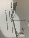
Illustrate Ram Pump Installation
Conditions required for Hydraulic Ram to work effectively.
The (h) must be more than ____, but should not exceed ___.
.66m; 6m
Conditions required for Hydraulic Ram to work effectively.
The drive pipe should be straight and laid to an even grade, and its length should be ____ times the available fall. The drive pipe must be long enough to ensure that when the recoil of water takes place more resistance is offered by removing water in the drive pipe than by the delivery valve and the water immediately above it.
6 -8 times
Conditions required for Hydraulic Ram to work effectively.
The amount of water available should be at least ______ the required supply and there must be a getaway for the waste water.
10 times
Conditions required for Hydraulic Ram to work effectively.
The height (H) to which the water is to be delivered should not, in general, be more than _____ times the available fall.
6 - 8 times
Conditions required for Hydraulic Ram to work effectively.
As a rule. the diameter of the drive pipe should be at least _____ the diameter of the delivery pipe.
twice
In calculating for the quantity of water delivered by a hydraulic ram, use the formula:
q=Q x h x e/H
where:
q = quanitity (in liters) delivered from the ram in a given time.
Q = Quantity in liters flowing to the ram in the same time
h = Head (in meters of water on inlet side of ram
H = height in meters
e = efficiency
To supply a ram, 300 liters of water per hour are available. The head of the ram is 2.0m and the height to which is raised is 6.00m, if the ram is assumed to have an efficiency of 60%, what quantity of water will be delivered per hour?
Ans
Q= 60 liters per hour
Centrifugal Pumps Fault Findings
Fault - Cause - Remedy of Action
No discharge - Lack of Prime - ___
Prime pump and suction line, allowing trapped air to escape through bleed vent
Centrifugal Pumps Fault Findings
Fault - Cause - Remedy of Action
No discharge - Excessive suction lift - ___
Check suction head. Reduce lift. And or increase pipe size to negate friction head. Check foot valve and suction pipe for obstruction.
Centrifugal Pumps Fault Findings
Fault - Cause - Remedy of Action
No discharge - Excessive discharge head - ______
Check total head. Ensure all valves open. Check piping for blockages. Ensure non-return valves are installed correct way round.
Centrifugal Pumps Fault Findings
Fault - Cause - Remedy of Action
No discharge - Speed too low - _____
Check that pump revolutions are consistent with recommendations.
Centrifugal Pumps Fault Findings
Fault - Cause - Remedy of Action
No discharge - Pump clogged - ____
Check that impeller is not clogged
Centrifugal Pumps Fault Findings
Fault - Cause - Remedy of Action
No discharge - Wrong direction of rotation - ____
Check pump is rotating in right direction.
Centrifugal Pumps Fault Findings
Fault - Cause - Remedy of Action
No discharge - Air Leaks - _______
Check suction pipe and connection for leaks. Check seal or gland.
Centrifugal Pumps Fault Findings
Fault - Cause - Remedy of Action
No discharge - Vapour lock - ______
Check fluid temperature to ensure that fluid in the suction line is not flashing to vapour when the pressure is reduced.
Centrifugal Pumps Fault Findings
Fault - Cause - Remedy of Action
Low Delivery - Air Leaks/vapour Leaks - ______
Check and rectify
Centrifugal Pumps Fault Findings
Fault - Cause - Remedy of Action
Low Delivery - Worn or clogged impeller - _____
Replace and correct
Centrifugal Pumps Fault Findings
Fault - Cause - Remedy of Action
Low Delivery - Incorrect Pipe size - _____
CHeck recommendation
Increase size reduce friction head
Centrifugal Pumps Fault Findings
Fault - Cause - Remedy of Action
Low Delivery - Blockage of construction - ____
check total head
Centrifugal Pumps Fault Findings
Fault - Cause - Remedy of Action
Low Delivery - Poor Suction - _____
Ask for recommendation
Centrifugal Pumps Fault Findings
Fault - Cause - Remedy of Action
Low Delivery - Wrong Pump - ______
Check Recommendation
Centrifugal Pumps Fault Findings
Fault - Cause - Remedy of Action
Low Pressure - Worn Impeller - ______
Check and replace
Centrifugal Pumps Fault Findings
Fault - Cause - Remedy of Action
Low Pressure - Wrong rotation - _____
Check and correct
Centrifugal Pumps Fault Findings
Fault - Cause - Remedy of Action
Low Pressure - FLow velocity - ______
Check recommendation
Centrifugal Pumps Fault Findings
Fault - Cause - Remedy of Action
Low Pressure - Unbalanced impeller - _____
Increase size to reduce friction head
Centrifugal Pumps Fault Findings
Fault - Cause - Remedy of Action
Low Pressure - Faulty bearings.bent shaft - ____
Check total head
Centrifugal Pumps Fault Findings
Fault - Cause - Remedy of Action
Low Pressure - Misalignment - ______
Ask for recommendation
Centrifugal Pumps Fault Findings
Fault - Cause - Remedy of Action
Low Pressure - Badly INstalled - _____
Check recommendation
Centrifugal Pumps Fault Findings
Fault - Cause - Remedy of Action
Vibration and Noise - Cavitation - ___
Check operation conditions, fluid temperature and NPSH
Centrifugal Pumps Fault Findings
Fault - Cause - Remedy of Action
Vibration and Noise - Incorrect rotation - _____
Check and rectify
Centrifugal Pumps Fault Findings
Fault - Cause - Remedy of Action
Vibration and Noise - Flow Velocity - _____
Increase pipe size. Reduce FLow
Centrifugal Pumps Fault Findings
Fault - Cause - Remedy of Action
Vibration and Noise - Unbalanced impeller - _____
Check for wear or clogging
Centrifugal Pumps Fault Findings
Fault - Cause - Remedy of Action
Vibration and Noise - Faulty bearings / bent shaft - ____
Replace if necessary
Centrifugal Pumps Fault Findings
Fault - Cause - Remedy of Action
Vibration and Noise - Misalignment - ____
Check alignment with prime-mover
Centrifugal Pumps Fault Findings
Fault - Cause - Remedy of Action
Vibration and Noise - Badly installed - _____
Centrifugal Pumps Fault Findings
Fault - Cause - Remedy of Action
Excessive Wear - Corrosion - ____
Check that pump material and fluid are compatible
Centrifugal Pumps Fault Findings
Fault - Cause - Remedy of Action
Excessive Wear - Cavitation - ____
check operating conditions
Centrifugal Pumps Fault Findings
Fault - Cause - Remedy of Action
Excessive Wear - Abbrassive fluid - _____
Ask for recommendations
Centrifugal Pumps Fault Findings
Fault - Cause - Remedy of Action
Heating Bearing - Running too fast - ______
Check maximum operating speed
Centrifugal Pumps Fault Findings
Fault - Cause - Remedy of Action
Heating Bearing - Belts too tight - ____
Slacken Tension
Centrifugal Pumps Fault Findings
Fault - Cause - Remedy of Action
Heating Bearing - Misalignment - ____
check alignment
Centrifugal Pumps Fault Findings
Fault - Cause - Remedy of Action
Heating Bearing - Lack of lubricant - _____
Repack with grease or replace
Centrifugal Pumps Fault Findings
Fault - Cause - Remedy of Action
Heating Bearing - Distortion - ____
Bearings too tight
A pumping system that provide water, within pre-set flow and pressure ratings, automatically on demand.
Hydro Pneumatic Pressure
Elements of Hydro Pneumatic System
A pump (of any type of manufacturer)
A pressure sensing electric switch - opens and closes the electrical contacts causing the pump to stop and start
Pressure vessel which contains an elastic medium. usually air.
Is defined as force per unit area, the area being measure at right angles to direction of the force. The unit of pressure N/m2 is called Pascal (Pa). Kilo Pascal (kPa)) and Mega Pascal (MPa) are commonly used.
Pressure
1000 Pa is equal to
1 kPa
is the height or vertical distance from the point of measurement to the free level of water in the system.
Head
occurs when the free water level is higher than the point of measurement.
Positive Head
Occurs where the free water level is lower than the point of measurement. It is also known as suction, partial vacuum or negative pressure.
Negative Head
Results from the vertical height of a column of water. It is the weight of water exerted as a result of the force of gravity. In pumping operations, it is the vertical distance (in meters) from the center line of the pump to the point of free discharge.
Static Discharge Head or Gravity Head
The vertical height to which a given pressure will force water to a certain level.
Pressure Head
The term used when the source of suuply is below the center line of the pump.
Suction Lift
The vertical distance from the liquid level to the center line of the pump.
Static Suction Lift
The static suction lift plus friction head in the entire suction pipe and fittings.
Total suction lift
The term used when the source of supply is above the center line of the pump. Also know as flooded suction.
Suction Head
the vertical distance (in meters) from the center line of the pump to the level of the liquid being pumped.
Static Suction HEad
the static suction head minus the friction head in the entire suction pipe and fittings.
Tota Suction Head
The static delivery head plus the friction head plus the friction head in all of the delivery pipe and fittings.
Total Discharge Head
the head required to accelerate the water in the delivery pipe. It should be included in the total pump head but it so nominal that it is usually ignored.
Velocity Head
the total suction lift plus the total delivery plus the velocity head.
Total Pump Head
There are a few different types of pumps used i plumbing applications to remove excess water and unwanted waste water.
The most commonly used pumps include: (4)
Sump Pumps
Effluent Pumps
Sewage Pumps
Grinder Pumps
- used to remove excess water in sump pits (also known as basins)
- Commonly used in flood prone basements of homes
- Are either submersible and pedestal
- Submersible pumps work while under water
- pedestal pumps are held up by supports and start operating when water reaches a certain level.
Sump Pumps
Used to transfer effluent wastewater, which is he gray waste water left over after solids have settled.
Commonly used in septic line and sanitary sump drainage applications.
Effluent Pumps
Used to remve liquids that contain solid pieces up to about 2 inches wide without getting clogged.
Commonly Used in sewarage, septic line, and drainage applications.
Sewage Pump
Used to break down solids into smaller pieces before being passed through.
Commonly used in light commercial and residential applications for wastewater from appliances (toilets, washing machines, bathtubs, etc.) to pass trhough.
Grinder Pumps
a water-tight receptacle which receives the discharge of a sanitary plumbing system or part hereof, designed and constructed to retain solids, digest organic matter through a period of detention and to allow the liquids to discharge into the soil outside of the tank through a system of open - jointed sub surface piping’s or a seepage pit meeting the requirements of the National Plumbing Code of the Philippines.
Septic Tank
The main function of a septic tank is to liquefy and precipitate solid waste purifying odorous materials. Sewage that was discharge into the tank is retained. And during its retention period, about _____ of the suspended solid of the sewage is removed largely by sedimentation to form a semi-liquid substance called sludge. The sludge accumulates at the bottom of the septic tank. Parts of the solids are formed into floating Scum. Both the scum and the sludge are processed by anaerobic bacteria and transforming them into liquid and gases.
60 - 70%
This process called digestion. The digestion the solid matter is reduced in size and consequenty changed in character. The septic therefore, combines two processes: ______ in the upper portion of the tank and _____ of the accumulated sludge at the bottom.
Sedimentation; Anaerobic Decomposition
Decomposition of organic matter from human waste is a bacteriological process caused by: (3)
Anaerobic Bacteria (Anaerobes)
Aerobic Bacteria (Aerobes)
Facultative Bacteria
The life process of Aerobic bacteria is in the _____. The anaerobic bacteria on the other hand, functions in the absence of _____. Likewise, Facultative bacteria also functions even ______.
Presence of material oxygen; free oxgen; with or without free oxygen
These three type of bacteria (Aerobes;anaerobes; facultative) have no relation to disease. They thrive naturally in sewage and will function when conditions are favorable in terms of: (3)
Food Supply
Temperature
Moisture
Discharge large amount of volume of waste and water containing ____ (3) into the septic tank will affect and disturb the bacterial activities therein and may then destroy the purpose for which the septic tank is constructed.
Disinfectant; Oil; and Grease
Human waste or excreta are decomposed until the organic matters are transformed into materials that could no longer be utilized by the bacteria in their life process. The process of decomposition is regarded as ____.
Stabilization
Decomposition caused by anaerobic bacteria which is sometimes referred to as ____, is accompanied by bad odors. On the other hand, aerobic decomposition is not accompanied by unpleasant odor.
Putrefaction
A sewage that turns dark and smell unpleasantly due to anaerobic decomposition is called _____. Decomposition caused by aerobic bacteria is acoomplished with no definite time and could be within a matter of hours.
Septic
is a combination of hydrogen and carbon, a principal component of natural gas.
Methane (CH4)
is combination of carbon and oxygen. It is the simplest oxide of carbon.
Carbon Dioxide (CO2)
is a by-product of methane, classified as poisonous gas.
Carbon Monoxide (CO)
evolves as a moist gas from organic waste.
Hydrogen (H2)
is a colorless gas with offensive odor.
Hydrogen Sulfide (H2S)
is also a colorless gas having an irritating odor.
Sulfur Dioxide (HO2)
It is vitally important to open and inspect your septic tank at least every _____ to make sure that the baffles are intact ad functional.
3 years
NPCP - Prvate Sewage Disposal System
“Septic tank shall have a minimum of ____ compartments.
2 compartments
NPCP - Prvate Sewage Disposal System
The inlet compartment of any septic tank shall be not less than ___ of the total capacity of the tank, nor less than ____ liquid capacity.
2/3; 2 m3
NPCP - Prvate Sewage Disposal System
“LIquid depth shall not be less than ____ meters or more than ____ meters”
0.60m; 1.80m
NPCP - Prvate Sewage Disposal System
“The secondary compartment of any septic tank shall have a minimum capacity of ____ and a maximum capacity of _____ of the total capacity of such tank.”
1m3 ; 1/3
NPCP - Prvate Sewage Disposal System
“In septic tank having over ____ capacity, the secondary compartment may be not less than _____ in length.”
6m3; 1.50m
NPCP - Prvate Sewage Disposal System
Access to each septic tank shall be provided by at least ____ manholes, with ___ in minimum dimension or by an equivalent removable coer slab. One access manhole shall be located oer the inlet and one access manhole shall be located over the outlet. Wherever a first compartment exceeds ____ in length, all additional manhole shall be provided over the baffle wall.
two manholes; 508mm; 3.70 meters
NPCP - Prvate Sewage Disposal System
The inlet and outlet pipe openings shall be not less in size than the connecting Sewer Pipe. The vertical leg of a round inlet and outlet fitting shall not be less in size than the connecting sewer pipe nor less than ______. A baffle type fitting shall have the equivalent cross-sectional area of the connecting sewer pipe and not less than a ______ horizontal dimension when measured at the inlet and the outlet pipe inverts.
104.6mm; 106.6mm
NPCP - Prvate Sewage Disposal System
The inlet and outlet pipe or baffle shall extend _____ abobve and at least ____ below the water surface. The invert of the inlet pipe shall be at a level not less than ____ above the invert of the outlet pipe.
101.6mm; 304.8mm; 50.8mm
NPCP - Prvate Sewage Disposal System
Inlet and outlet pipe fittings or baffles, and compartment partitions shall have a free vent area equal to the required cross-sectional area of the house sewer or private sewer discharging there into to provide free ventilation above the water surface from the disposal field or seepage pit through the septic tank, house sewer, and slack to the outer air.
NPCP - Private Sewage Disposal
The side walls shall extend at least __ above the liquid depth. The cover of the septic tank shall be at least ____ above the back vent openings.
228.6mm; 50.8mm
NPCP - Private Sewage Disposal
Partitions or baffles between compartments shall be of solid durable material and shall extend at least _____ above the liquid level. An inverted fitting equivalent in size to the tank inlet, but in no case less than _____ in size, shall be installed in the inlet compartment side of the baffle with the bottom of the fitting placed midway in the depth of the liquid. ____ baffles are prohibited.
101.6mm; 104.6mm; wood
Each such tank shall be structurally designed to withstand all anticipated earth of other loads. All septic tank covers shall be capable of supporting an earth load of not less than ____ when the maximum coverage does not exceed ____.
14.4 kPa; 9 meters
1 inch to mm
25.4mm
1 psi = __ kPa
6.89 kPa
Minimum horizontal distance in Clear required from:
Buildings or Structures to Building Sewer
.60m
Minimum horizontal distance in Clear required from:
Buildings or Structures to Septic Tank
1.5m
Minimum horizontal distance in Clear required from:
Buildings or Structures to Disposal Field
2.4m
Minimum horizontal distance in Clear required from:
Buildings or Structures to Seepage Pit or Cesspool
2.4m
Minimum horizontal distance in Clear required from:
Property line adjoining private property to Building Sewer
Clear
Minimum horizontal distance in Clear required from:
Property line adjoining private property to Septic Tank
1.5m
Minimum horizontal distance in Clear required from:
Property line adjoining private property to Disposal Field
1.5m
Minimum horizontal distance in Clear required from:
Property line adjoining private property to Seepage Pit or Cesspool
2.4m
Minimum horizontal distance in Clear required from:
Water Supply Wells to Building Sewer
15.2m
Minimum horizontal distance in Clear required from:
Water Supply Wells to Septic Tank
15.2m
Minimum horizontal distance in Clear required from:
Water Supply Wells to Disposal Field
30.5m
Minimum horizontal distance in Clear required from:
Water Supply Wells to Seepage Pit or Cesspool
45.7m
Minimum horizontal distance in Clear required from:
Streams to Building Sewer
15.2m
Minimum horizontal distance in Clear required from:
Streams to Septic Tank
15.2m
Minimum horizontal distance in Clear required from:
Streams to Disposal Field
15.2m
Minimum horizontal distance in Clear required from:
Streams to Seepage Pit or Cesspool
30.5m
Minimum horizontal distance in Clear required from:
Trees to Building Sewer
-
Minimum horizontal distance in Clear required from:
Trees to Septic Tank
3m
Minimum horizontal distance in Clear required from:
Trees to Disposal Field
-
Minimum horizontal distance in Clear required from:
Trees to Seepage Pit or Cesspool
3m
Minimum horizontal distance in Clear required from:
Seepage Pits or Cesspool to Building Sewer
-
Minimum horizontal distance in Clear required from:
Seepage Pits or Cesspool to Septic Tank
1.5m
Minimum horizontal distance in Clear required from:
Seepage Pits or Cesspool to Disposal Field
1.5m
Minimum horizontal distance in Clear required from:
Seepage Pits or Cesspool to Seepage pit or Cesspool
3.7m
Minimum horizontal distance in Clear required from:
Disposal Field to Building Sewer
-
Minimum horizontal distance in Clear required from:
Disposal Field to Septic Tank
1.5m
Minimum horizontal distance in Clear required from:
Disposal Field to Disposal Field
1.2m
Minimum horizontal distance in Clear required from:
Disposal Field to Seepage Pit or Cesspool
1.5m
Minimum horizontal distance in Clear required from:
On site domestic water service line to Building Sewer
.3m
Minimum horizontal distance in Clear required from:
On site domestic water service line to Septic Tank
1.5m
Minimum horizontal distance in Clear required from:
On site domestic water service line to Disposal Field
1.5m
Minimum horizontal distance in Clear required from:
On site domestic water service line to Seepage Pit or Cesspool
1.5m
Minimum horizontal distance in Clear required from:
Distribution Box to Building Sewer
-
Minimum horizontal distance in Clear required from:
Distribution Box to Septic Tank
-
Minimum horizontal distance in Clear required from:
Distribution Box to Disposal Field
1.5m
Minimum horizontal distance in Clear required from:
Distribution Box to Seepage Pit or Cesspool
1.5m
Minimum horizontal distance in Clear required from:
Pressure Public Water Main to Building Sewer
3 m
Minimum horizontal distance in Clear required from:
Pressure Public Water Main to Septic Tank
3m
Minimum horizontal distance in Clear required from:
Pressure Public Water Main to Disposal Field
3m
Minimum horizontal distance in Clear required from:
Pressure Public Water Main to Seepage Pit or Cesspool
3m
NSCP - Location of Sewage Disposal System
When dosposal fields and/or seepage pits are installed in sloping ground, the minimum horizontal distance between any part of the leaching system and ground surface shall be ___.
4.6m
NSCP - Location of Sewage Disposal System
All drainage piping shall clear domestic water supply wells by at least ____. THis distance may be reduced to not less than ____ when the drainage piping is constructed of materials approved for use within a building.
15.2m; 7.6m
Estimated Waste/Sewage Flow Rates for:
Airports
tile per employee
lo per passenger
Estimated Waste/Sewage Flow Rates for:
Autowashers
Check with equipment manufacturer
Estimated Waste/Sewage Flow Rates for:
Bowling alleys (snack bar only)
kola per lane
Estimated Waste/Sewage Flow Rates for:
Campground with central comfort station
Mile per person
Estimated Waste/Sewage Flow Rates for:
Camps with flush toilets, no showers
nil per person
Estimated Waste/Sewage Flow Rates for:
Day camps (no meal served)
tile per person
Estimated Waste/Sewage Flow Rates for:
Camps (summer and seasonal)
Lice per person
Estimated Waste/Sewage Flow Rates for:
Churches (Sanctuary)
lo per seat
Estimated Waste/Sewage Flow Rates for:
Churches with kitchen waste
kea per seat
Estimated Waste/Sewage Flow Rates for:
Dance halls
lo per person
Estimated Waste/Sewage Flow Rates for:
Factories with no showers
nil per employee
Estimated Waste/Sewage Flow Rates for:
Factories with showers
mile per employee
Estimated Waste/Sewage Flow Rates for:
Factories with cafeteria
lo per employee
Estimated Waste/Sewage Flow Rates for:
Hospitals
nils per bed
Estimated Waste/Sewage Flow Rates for:
Kitchen waste only
Nil per bed
Estimated Waste/Sewage Flow Rates for:
Hospital - laundry waste only
rose per bed
Estimated Waste/Sewage Flow Rates for:
Hotels with no kichen wate
gas per bed (2 person)
Estimated Waste/Sewage Flow Rates for:
Institutions (Residents)
Kola per person
Estimated Waste/Sewage Flow Rates for:
Nursing Home
Tonal per person
Estimated Waste/Sewage Flow Rates for:
Rest Home
tonal per person
Estimated Waste/Sewage Flow Rates for:
Laundries, self service with minimum 10 hours per day
lice per wash cycle
Estimated Waste/Sewage Flow Rates for:
Laundries, self service - Commercial
per manufacturer’s specification
Estimated Waste/Sewage Flow Rates for:
Motel
lice per bed space
Estimated Waste/Sewage Flow Rates for:
Motel with kitchen
gas per bed space
Estimated Waste/Sewage Flow Rates for:
Offices
nice per employee
Estimated Waste/Sewage Flow Rates for:
Parks, mobile homes
nils per space
Estimated Waste/Sewage Flow Rates for:
Picnic parks (toilets only)
nice per parking space
Estimated Waste/Sewage Flow Rates for:
Parks - recreation vehicles without hook up
kola per space
Estimated Waste/Sewage Flow Rates for:
Parks, recreational vehicles with water and sewer hook up
Toss per space
Estimated Waste/Sewage Flow Rates for:
Restaurants - cafeterials
nice per employee
Estimated Waste/Sewage Flow Rates for:
Restaurants with toilet
kea per customer
Estimated Waste/Sewage Flow Rates for:
Restaurang with kitchen waste
go per meal
Estimated Waste/Sewage Flow Rates for:
Restaurants - add for garbage disposal
do per meal
Estimated Waste/Sewage Flow Rates for:
Restaurants - add for cocktail lounge
no per customer
Estimated Waste/Sewage Flow Rates for:
Restaurant - Kitchen Waste - disposable service
no per meal
Estimated Waste/Sewage Flow Rates for:
Schools - staff and office
nice per person
Estimated Waste/Sewage Flow Rates for:
School - Elementary students
tile per person
Estimated Waste/Sewage Flow Rates for:
School - intermediate and high school
nice per student
Estimated Waste/Sewage Flow Rates for:
Shools with gym and showers, add
lo per student
Estimated Waste/Sewage Flow Rates for:
Schools - Intermediate and high school with cafeteria, add
me per student
Estimated Waste/Sewage Flow Rates for:
Schools with boarding, total wsate
toss per person
Estimated Waste/Sewage Flow Rates for:
Service station, toilets
toss us for 1st bay, lices for each additional bay
Estimated Waste/Sewage Flow Rates for:
Stores
nice per employee
Estimated Waste/Sewage Flow Rates for:
Stores with Public Restrooms, add
do per sq. m
Estimated Waste/Sewage Flow Rates for:
Swimming pools, public
tic per person
Estimated Waste/Sewage Flow Rates for:
Theaters, auditoriums
lo per seat
Estimated Waste/Sewage Flow Rates for:
Drive-in
tic per space
Sewage dosposal systems sized using the estimated waste/sewage flow rates should be calculated as follows:
Waste/sewage flow, up to 5677.5L(1500 gal)/day use formula:
Flow x 1.5 = septic tank size
note: all inputs (eg. flow) must be in liters, therefore convert gallons to liters.
Sewage dosposal systems sized using the estimated waste/sewage flow rates should be calculated as follows:
Waste/sewage flow, over 5677.5L(1500 gal)/day use formula:
Flow x 0.75 / 1125 = septic tank size
note: all inputs (eg. flow) must be in liters, therefore convert gallons to liters.
A device for removing fat and grease from waste water by allowing the retained liquid to cool and the grease to solidify to a maximum of ____; then the grease is separated by floatation; it is rises to the top of the trap, where it is held. The prime purpose is to assure a free flowing drainage through pipe lines at all times by intercepting, accumulating and recovering globules of grease fat and oil from waste water.
Grease Trap
is a device designed and installed to separate and retain deleterious, hazardous or undesirable matters from normal wastes and permits normal sewage or liquid waste to discharge into the disposal terminal by gravity.
Clarifier/Interceptor
NPCP - Grease Traps
When in the judgement of the administrative authority, waste pretreatment is required, an approved type ____ complying with the provisions of this sections shall be installed in the waste line leading from sinks, drains and other fixtures or equipment in establishments such restaurants, cafes, lunch counters, cafeterias, bars and clubs, hotel hospital, sanitarium, factory or school kichens, or other establishments where grease may be introduced into the drainage or sewer system in quantities that can effect line stoppage or hinder sewage treatment or private sewage disposal. A grease trap is not required for ________ or to any private living quarters.
Grease Trap; Individual dwelling Units
NPCP - Grease Traps
No individual grease trap shall be installed for a facility that has an approved rate of flow of more than _______ nor less than _____ except when specially approved by the Administrative Authority.
3.4 L/s; 1.3 L/s
NPCP - Grease Traps
Each plumbing fixture or piece of equipment connected to a grease trap shall be provided with an approved type _______ installed in a readily accessible and visible location in the tailpiece or drain outlet of each such fixture. This devices shall be sodesigned that the flow through such device or devices shall at no time be greater than the rated capacity of the grease trap. No flow control device having adjustable or removable part shall be approved.
Flow control or restricting deviceFlow control or restricting device
NPCP - Grease Traps
Each grease trap required by this section shall have an approved rate of flow which is not less than that given in table 10-2 for the total number of connected fixtures. The total capacity of fixtures discharging into any such grease trap shall not exceed _____ times the certified liters per minute flowrate of the grease trap as per table 10-2.
2 1/2 times
NPCP - Grease Traps
Any grease trap installed with inlet more than _____ lower in elevation than the outlet of any fixture discharging into such grease trap shall have an approved rate of flow which is not less than ______ nor more than four (4) separage fixture shall be connected to or discharged into any one grease trap.
1.2 meters; 50% greater than that given in table 10-2
Illustrate and label trable 11 @ yellow.
Grease Trap Capacity
NPCP - Grease Traps
Each fixture discharging into a grease trap shall be individually trapped and vented in an approved manner. An approved-type grease trap may be used as a fixture outlet and the grease trap for a single fixture when the horizontal distance between the fixture outlet and the grease trap does not exceed _____ and the vertical tairpipe or drain doesnot exceed _____.
1.2 meters; .75 meters
Grease traps shall be maintained in efficient operating condition by periodic removal of the accumulated grease and settled solids. No such collected grease shall be introduced into the drainage piping and public or private sewer.
NPCP - Grease Traps
No _____ grease trap or grease interceptor shall be approved or installed.
water jacketed
NPCP - Grease Traps
Each grease trap shall have an approved water seal of not less than ____ depth or the diameter of its outlet, whichever is greater.
51mm
NPCP - Food waste disposal prohibited
Unless specifically required or permitted by the Administrative Authority, no _____ shall be connected to or discharge into any grease interceptor or grease trap.
food waste disposal unit
Illustrate Drainage Accesories for Institutional Kitchen
See phone gallery
Formula for Grease and Garbage, Commercial Kitchens
Numberber of Meals per peak hour x Waste Flow Rate x Retention Time x storage factor = Interceptor Size (Liquid Capacity)
Formula for Sand-Silt Oil; Aito Washers
number of vehicles per hour x waste flow rate x retention time x storage factor
Formula for Silt-lint Grease, Laundries, Laundromats
number of machines x 2 cycles per hour x waste flow rate x retention time x storage factor = interceptor size (liquid capacity)
Commercial Kitchen waste - Dishwasher and/or disposal
2.5 hours
Retention time for:
Single service kichen - Single serving with disposal
1.5 hours
Retention time for:
Sand Silt Oil
2 hrs
Retention time for:
Lint Silt (Laundry)
2 hrs
Storage Factors:
Fully equipped commercial kitchen
8 hr operation
1
Storage Factors:
Fully equipped commercial kitchen
16 hr operation
2
Storage Factors:
Fully equipped commercial kitchen
24 hr operation
3
Storage Factors:
Single Service Kitchen
1.5
Storage Factors:
Auto Washers - Self Serve
1.5 hrs
Storage Factors:
Autowashers - employee operated
2
Storage Factors:
Laundries, laundromats
1.5 (allows for rock filter)
a pipe or opening used for ensuring the circulation of air in a plumbing system and for relieving the negarive pressure exereted on trap seals.
Vent Pipe
a system of pipes supplying a flow of air to or from a drainage system or providing a circulation of air within the system to protect trap seals from siphonage.
vent system
an oversized pipe functioning both as a soil or waste pie and a vent.
wet vent
a vent that does not carry liquid or water borne wastes
dry vent
a vent that provides circulation of air between drainage and a venting system by connecting a vent stack to a horizontal drain between the first fixture and the soil or waste stack.
Relief vent
a circuit vent that loops back and connects with a stack vent instead of a vent stack
loop vent
a group vent pipe which starts in front of the extreme fixture connection on a horizontal branch and connects to the vent stack.
Circuit Vent
the part of a vent line, which connects directly with an individual trap underneath or behind the fixture and extends to the branch or main vent pipe at any point higher than the fixture or fixture traps it serves.
Back/Revent/Individual Vent
is a pipe installed to vent fixture trap and which connects with the vent system above the fixture solved or terminates in the open air.
Individual vent
an arrangement of venting so installed that one vent pipe will serve two traps.
Dual/Common/unit vent
A branch vent that performs its functions for 2 or more traps.
Group vent
the principal artery of the venting system to which vent branches are connected.
Main vent
A vertical vent line, the primary function of which is to provide additional circulation of air between the drainage and vent systems or to act as an auxiliary vent on a specially designed system such a “Yoke vent” connection between the soil and vent stacks.
Relief vent
a pipe connecting upward from a soil or waste stack below the floor and below horizontal connection to an adjacent vent stack at a point above the floor and higher than highest spill level of fixtures for preventing pressure changes in the stacks.
Yoke Vent
the extension of a soil or waste stack above the highest horizontal drain connected to the stack. The uppermost end above the roof is called stack vent through roof. (SVTR)
Stack Vent
the vertical vent pipe installed primarily for providing circulation of air to and from any part of the soil, waste of the drainage system.
NPCP - Vent Termination
Each vent pipe or stack through roof (SVTR) shall extend its flashing all around and the stack vent shall terminate vertically not less than ____ above the roof nor less than ____ from any vertical surface nearby.
15cm; .3 meters
Each vent opening shall terminate not less than ____ from, or atleast ____ above any openable window, door opening, air intake or vent shaft; nor less than ___ away from any lot line, alley and street boundary lines.
3 meters; 0.90 meters; 0.90 meters
NPCP - Vent Termination
Vent pipes shall be extended separately or combined, of full required size not less than ____ above the roof or fire wall. ____ of vents is prohibited except where the roof is used for purposes other than weather protection.
15cm; Flagpoint
Vertical vent pipes for outdoor installation shall esxtend to at least ____ distant from any part of the roof that is used for other purposes and shall extend not less than ___ above such roof and shall be securely stayed.
3 meter; 2.1 meter
NPCP - Vent Termination
Joint at the roof around stack vent pipes shall be made ____ by the use of approved flashing material and installation.
watertight
a vertical pipe to convey rainwater.
Conductor/Downspout
the vertical portion of a rainwater conductor.
Downspout
a pipe connected from building gutter to the downspout or conductor.
Leader
NPCP - Sizing or Rainwater Piping
Vertical rainwater piping shall be sized in accordance with Table 11-1, which is based upon maximum depth in mm of rainfall per hour falling upon a given roof area in square meter. Consult local rainfall figures to determine maximum rainfall per hour. Normally ___ mm/hour rainfall intersity used around Manila Area.
102
NPCP - Sizing or Rainwater Piping
Vertical Wall Area. Where vertical walls project above a roof so as to permit storm water to drain to adjacent roof area below, the total roof area considered may be computed from Table 11-2 as follows:
For one wall - add ____ of area of the wall to the roof area
50%
NPCP - Sizing or Rainwater Piping
Vertical Wall Area. Where vertical walls project above a roof so as to permit storm water to drain to adjacent roof area below, the total roof area considered may be computed from Table 11-2 as follows:
For two adjacent walls - add ___ of the total wall areas to the roof area.
35%
NPCP - Sizing or Rainwater Piping
Vertical Wall Area. Where vertical walls project above a roof so as to permit storm water to drain to adjacent roof area below, the total roof area considered may be computed from Table 11-2 as follows:
Two walls opposite each other and of same heights - add _____ area to the roof area
no additional area
NPCP - Sizing or Rainwater Piping
Vertical Wall Area. Where vertical walls project above a roof so as to permit storm water to drain to adjacent roof area below, the total roof area considered may be computed from Table 11-2 as follows:
Two walls opposite of differing heights - add ____ of wall area above top of lower wall to the roof area.
50%
NPCP - Sizing or Rainwater Piping
Vertical Wall Area. Where vertical walls project above a roof so as to permit storm water to drain to adjacent roof area below, the total roof area considered may be computed from Table 11-2 as follows:
Walls on three sides - add ____ of area of the inner wall below the top of the lowest wall, plus alloawnce for area of wall above top of the lowest wall.
50%
NPCP - Sizing or Rainwater Piping
Vertical Wall Area. Where vertical walls project above a roof so as to permit storm water to drain to adjacent roof area below, the total roof area considered may be computed from Table 11-2 as follows:
Walls of four sides - no allowance for wall areas below top of lowest wall - add for areas above top lowest wall.
NPCP - Sizing or Rainwater Piping
Vertical Wall Area. Where vertical walls project above a roof so as to permit storm water to drain to adjacent roof area below, the total roof area considered may be computed from Table 11-2 as follows:
The area of the side of a tall building exposed to rain is taken as ____ of the gross area.
1/2