Systems Test 3 Flashcards
- LOT 201.14 PZR Pressure & Level*
- *
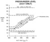
At what pressure will the PORV (PCV-655A) lift when COMS is armed?
- 70 - 200 ˚F:*
- *515 psig**
- 220 - 380 ˚F:*
- *730 psig**
Uses Auct Low WR TH / PT-403
- Note:*
- Normal PORV setpoint is ≈ 2335 psig. (Master pressure controller 87.5%)*

- LOT 202.36 Essential Chilled Water*
- *
When will the running and standby essential chillers start on a LOOP / SI? (ESF DG Sequencer)
- Standby:*
- *35 sec**
- (Chilled Water Pump / Chiller Oil Pump)*
- *65 sec (30 sec prelube cycle)**
- Essential Chiller*
- Running:*
- *240 sec**
- (Chilled Water Pump / Chiller Oil Pump)*
- *270 sec (30 sec prelube cycle)**
- Essential Chiller*
Running essential chiller must complete 135 sec post lube cycle before it can be restarted on ESF DG sequencer.
Note:
ESF sequencer bypasses the 30 min anti-recycle timer permissive
- LOT 201.27 Containment Combustible Gas*
- *
What are the sources of H2 during a LOCA?
- Major Source:*
- *Radiolytic decomposition of water ****
Other Sources:
Zirc water reaction **
H2 from the RCS
Max is 1190 scf
Corrosion of metals and paint in containment
Zinc-based paints & galvanized steel
Aluminum
Less of a source than zinc
- Note:*
- Radiolytic decomposition of water and Zirc water reaction are variable and will increase with fuel damage*
- LOT 201.18 Rod Control*
- *
What does the Rod Control Startup Switch reset?
- POSSUM:*
- *P/A Converter**
- *Bank Overlap Unit**
- *Step Counters**
- *Slave Cyclers**
- *Urgent Failures**
- *Master Cycler**

Located on CP005.
- LOT 201.18 Rod Control*
- *
How is the Terror signal generated in the Rx Control Unit?
- Terror = (Tref - Tave) + (Turb Load - NI power)*
- *Tref → Turbine Impulse Pressure (PT-505)**
- *Tave → Auctioneered High Tave (T-412A/422A/432A/442A)**
- *Turb Load → Turbine Impulse Pressure (PT-505)**
- *NI Power → Auctioneered High PR NIs (NI-41/42/43/44)**
- Turbine Load - NI Power Portion:*
- *Used for fast response during transients / load stability**
- *Passes through Rate comparator**
- Rate of change produces error output*
- Steady state results in no output*
Note:
Terror meter on CP005

- LOT 201.13 ECW*
- *
What will auto start/stop the ECW pumps?

- Auto Start:*
- *ESF DG Sequencer (25 Sec)**
- MODES I, II, III*
- *CCW Header Pressure - Low (76 psig) [15 sec TD]**
- *ECW Header Pressure - Low (30 psig) [2/3] [15 sec TD]**
- Low Pressure on other two trains*
- Auto Stop:*
- *Discharge Valve not 95% open after 25 sec**
- N/A for SI*
- Note:*
- 15 Sec TD is to prevent inadvertant train S/U during transient conditions.
- Discharge valve must be open after 25 sec b/c ECW pump does not have a recirc line to protect the pump
- LOT 202.36 Essential Chilled Water*
- *
What ECW pond temperature would make the Essential Chilled Water system inoperable?
< 41 ˚F
Per POP02, declare inoperable in MODES 1 - 4.
- LOT 201.18 Rod Control*
- *
What provides an accurate indication of control rod bank step count positions by counting the up down pulses from the Rx Control Unit?
Pulse to Analog Converter
Located in back of DC hold cabinet.
- Note:*
- During Rx S/U, resets when operators reset the S/U Switch.
- During Dropped rod, have to use manual mode to reset bank to height of dropped rod

- LOT 201.12 CCW*
- *
What are the important levels in the CCW Surge Tank?
- 83.3%:*
- *High Alarm**
- 74%:*
- *Makeup Valve Closes**
- 68.75%:*
- *Makeup Valve Opens**
- 66.7%:*
- *Low Alarm**
- 64.6%:*
- *1st Low Level Isolation**
- 61.5%:*
- *2nd Low Level Isolation**
- 56%:*
- *Baffles Begin**
- 49%:*
- *Compartment Level - Low Alarm**
- 8.3%:*
- *Compartment Level - Low 2 Alarm**
- Demin water normally fills CCW Surge Tank. (Auto)
- RMWST can fill the CCW Surge Tank. (Manual)

- LOT 201.14 PZR Pressure & Level*
- *
What is the basis for the size of the PZR?
- Enough Water:*
- *Keep Heaters covered during step load increase of 10%**
- Enough Steam:*
- *Accomodate 50% load reduction w/o reaching PZR LVL - High (92%)**
- w/ Rods and Steam Dumps*
- *After PZR LVL - High (92%) Rx trip, will not lift safety valves**
- After Rx Trip AND Turbine Trip:*
- *No SI**
- *PZR will not empty**
- LOT 201.07 Rx Makeup System*
- *
What will make the makeup stop valves (FCV-0110B/FCV-0111B) auto close?

- Total Makeup Flow Deviation:*
- *± 15 gpm [15 sec TC]**
- BA Flow to Blender Deviation:*
- *± 2 gpm [15 sec TC]**
- LOT 201.09 RHR*
- *
What happens in the RHR system during a SI?
RHR HX Bypass Closes
RHR HX TCV Valve Full Open
RHR Pumps Trip
- *CCW from RHR HX opens**
- CCW pump mini-flow concerns*

- LOT 201.12 CCW*
- *
What will cause the thermal barrier isolation valve to shut?
CCW Flow - High (60 gpm)
CCW Temp - High (187 ˚F)
Protects CCW piping from thermal barrier HX leak.
Switches located on CP004.
Two in-line backpressure sensing valves provide backup
- Start to close at 120 psig
- Full close at 150 psig
- Note:*
- Backpressure sensing valves auto-reset when pressure drops below setpoint*

- LOT 201.10 ECCS*
- *
What is the system lineup during hot leg recirc?
2 ECCS trains injecting into Hot Legs
1 ECCS train injecting into Cold Leg
LHSI and HHSI mini-flow valves closed
Taking Suction from Emergency Sumps
HHSI and LHSI are operated together. Never align HHSI to Hot leg and LHSI to Cold leg or vice versa.
- Note:*
- Cold Leg Recirc is the exact same except all 3 ECCS trains injecting into cold legs.*
- LOT 202.38 FHB HVAC*
- *
What cools the components in the FHB HVAC System?
- MAB Chill Water:*
- *FHB HVAC Supply**
- *Temporary FHB Supplemental Cooling AHU**
- Only used to reduce heat during cask loading*
- Essential Chill Water:*
- *ECCS Pump Room**
- *Recirc Valve Room**
- *SF Pump Room**
- TSC Chill Water:*
- *PASS Station**
- LOT 201.09 RHR*
- *
Which RHR trains are used to transfer refueling water from the refueling cavity to the RWST at the end of a refueling operation?
RHR Train “B”
RHR Train “C”
Flow is controlled by throttling the respective train IRC or ORC isolation valve to the RWST
Note:
Do not use train that is selected for shutdown cooling.

- LOT 201.10 ECCS*
- *
What are the four phases of a DBA LOCA?
- *Blowdown**
- Begins with LOCA and ends with RCS pressure = CTMT pressure*
- *Refill**
- Water at bottom of the reactor vessel and reaches the bottom of the fuel rods via addition of ECCS (Accumulators and SI pumps).*
- *Reflood**
- Rx vessel filled with water*
- Core temperature rise has terminated*
- Core temperatures have been reduced to their long term steady state level.*
- *Long Term Recirculation**
- Cold Leg Recirc (1st Phase)*
- Hot Leg Recirc (2nd Phase)*
- Hot Leg Recirc starts 5.5 hrs (Operator Action) after start of LOCA and cools upper head and prevents boron precipitation.*
- LOT 201.14 PZR Pressure & Level*
- *
How many PZR heaters are there and what is the KW rating / heater?
117 Heaters
- *17.95 KW / Heater**
- 2101 KW Total*
LCO 3.4.3 PZR
Applicable MODES 1-3
- Requires 2 groups (A/B) w/ 175 KW each

- LOT 201.09 RHR*
- *
What trips the RHR pumps?
SI
RHR Flow - Low (925 gpm [5 sec TC])
CP001 Indications:
- Amps
- Flow
- LOT 201.10 ECCS*
- *
What are the Emergency Core Cooling System (ECCS) acceptance criteria?
Coolable Geometry
Long-Term cooling
Cladding Oxidation
≤ 17% the total cladding thickness before oxidation.
- *Peak Cladding Temperature**
- ≤ 2200 ˚F*
- *H2 Generation**
- ≤ 1% the total amount of H2 produced from all metal surrounding the fuel reacting*
- (excludes metal around plenum volume)*
DBAs:
- LOCA
- SLB
- Fuel Handling Accident
- LOT 201.07 Rx Makeup System*
- *
What will auto close the RMW non-essential service isolation valves? (FV-7663/FV-7659)

- *SI**
- SI Train “B” (FV-7663)*
- SI Train “C” (FV-7659)*
RMWST Level (54%)
RMWST Level (54%) will also isolate the RMWST sample line (FV-7664). (SI will not)
- Note:*
- Makeup to CCW surge tank and SFP will NOT be secured.*

- LOT 201.13 ECW*
- *
What is the minimum level and max temperature of the ECW pond as required by LCO 3.7.5 Ultimate Heat Sink?
- Level:*
- *≥ 25.5 ft**
- Max Level 26 ft (FSAR)*
- Temperature:*
- *≤ 99 ˚F**
Pond sized to have a 30 day cooling water supply to safely shutdown and cooldown both Units while maintaining a heat sink for heat removal
- Note:*
- ECW Bay LVL indication and alarms located on CP002
- ECW Bay LVL - Low 2 (14.96 ft) for LCO 3.7.5 entry.

- LOT 202.37 EAB/CR HVAC*
- *
During a DBA, what must control room personnel dose be limited to IAW 10CFR50?
≤ 5 Rem Whole Body
- LOT 201.10 ECCS*
- *
What valves in the ECCS have a power lockout feature?
- *HHSI/LHSI Hot leg injection valves (MOV-008/MOV-019)**
- 100% Power: Closed w/ power locked out*
- CP-001*
- *Accumulator outlet valves (MOV-039)**
- 100% Power: Open w/ power locked out*
- CP-001 / ASP*
No accumulator pressure / level indicators exist on ASP!!
- Note:*
- 2 transfer switches for accumulator outlet valves. 1 transfers control and VPI and the other transfers power lockout feature.*

- LOT 201.12 CCW*
- *
What will happen in the CCW system during a SI?
- *All 3 CCW pumps start**
- 20 Sec on ESF DG Sequencer*
- Will start even if switches on CP001/CP002 are in off*
- *Opens CCW HX outlet and closes bypass valves**
- Full flow through HX*
Isolates non-ESF loads
- *Aligns CCW to RCFCs**
- Secures RCB Chill Water*
- *Opens RHR HX outlet valves**
- CCW Min Flow requirements*
- Note:*
- Must re-align cooling to SFP HXs in 2.5 hrs.*

- LOT 201.08 BTRS*
- *
What is the limiting temperature and component for the BTRS?
130 ˚F
RCP Seals
Limit temperature to 115 ˚F to allow CCPs to add 15 ˚F.
- LOT 201.12 CCW*
- *
What will happen in the CCW system when the CCW Surge tank reaches 61.5%? (2nd Low Level Isolation)
- *Isolates CCW Header**
- Isolates RCP Upper/Lower Bearing Coolers, Thermal Barrier, RCP Motor Air Coolers, SFP HX, PASS Coolers*
CCW Train “B” → CCP “B” and Seal Water HX
CCW Train “C” → CCP “A” and PDP
- *Opens RHR Outlet Valves for running CCW Pumps ONLY**
- Min flow requirements*
- Note:*
- As soon as CCW common header isolated, standby CCW pump will start on CCW Header Pressure - Low (76 psig)*

- LOT 201.10 ECCS*
- *
What will cause an SI auto recirculation signal?
SI Signal
AND
- *RWST Level - Low 2 (≤ 75,000 gal) [1/1]**
- Each lvl switch provides signal for it’s train only*
Closes HHSI AND LHSI pump mini-flow valves.
When ≥ 1 valve for each pump closed:
- Opens containment sump → SI suction header Isolation valve.
RWST → SI suction header isolation valve must be manually closed by operator. (CP001)
- Note:*
- Reset and RWST lvl indication are located on CP001*

- LOT 201.13 ECW*
- *
What will happen in the ECW system once a ECW pump is started?
Starts self cleaning strainer motor
- *Starts to Open Discharge Valve after 10 sec**
- If not open after 25 sec, pump trips (N/A for SI)*
Opens chemical injection valve for associated bay
- *Opens Blowdown Valves (N/A for train 2A)**
- Maintain CP002 switches in CLOSE so doesn’t really happen*
- *Starts ventilation fans**
- Must be manually secured*
- Discharge Valve MCC switch in local prevents discharge valve opening when ECW pump starts.
- Self Cleaning strainer does not have switch in MCR.
- Note:*
- Discharge valve will shut 2 mins after ECW pump secures to prevent draining ECW piping to ECW pond and thus preventing water hammer on pump S/U.*
- LOT 201.13 ECW*
- *
What will cause a CCW standby train not selected alarm on CP002?
2 ECW/CCW train selector switches in “OFF”

- LOT 201.18 Rod Control*
- *
What causes a rod control power cabinet urgent failure?
- *Logic Error**
- 0 Current sent to stationary and movable grippers at same time*
- *Regulation Error**
- Current doesn’t match order or Full current for too long*
- *Phase Failure**
- Excessive voltage ripple*
- *Multiplex Error**
- Wrong rod getting current*
- *Rod Holdout switches out of position**
- *Loose Circuit Card**
- Stops Auto/Manual rod motion
- Individual Bank rod motion will still work
- Sends reduced current signal to affected group movable/stationary grippers
- Note:*
- Non-Urgent is a loss of 1 of the 4 power supplies and will not affect system operation.*
- LOT 201.14 PZR Pressure & Level*
- *
What Tavg is used to calculate PZR program level?
Auctioneered High Tavg
Compares selected controlling channel level (LT-465 or LT-467) to program level to determine demand to FCV-0205.
- LOT 202.38 FHB HVAC*
- *
How many FHB HVAC exhaust trains must be OPERABLE during movement of irradiated fuel?
- *One Train**
- *OR**
- *One Train Capable of being OPERABLE in 2 hrs**

TRM 3.9.12 FHB Exhaust Air System
- LOT 201.14 PZR Pressure & Level*
- *
What is the effect of indicated PZR level for the following conditions?
- Reference Leg Break
- Diaphragm Failure
- Reference Leg Heating
- Reference Leg Break:*
- *Less Mass → D/P ↓ → Lind↑**
- Diaphragm Failure:*
- *D/P ↓ → Lind↑**
- Reference Leg Heating:*
- *Less Mass → D/P ↓ → Lind↑**
- w/o compensation*
- LOT 201.14 PZR Pressure & Level*
- *
What are the important PZR Master pressure controller setpoints?
- PCV-655A:*
- *87.5%: Opens**
- *75%: Closes**
- Spray Valves:*
- *72%: Full Open**
- *40.5%: Start to Open**
- Control Heaters:*
- *34.5%: Zero Power**
- 22%: NOP*
- *15.5%: Full Power**
- B/U Heaters:*
- *14.5%: Turn Off**
- *9.5%: Turn On**

- LOT 202.38 FHB HVAC*
- *
What will cause a FHB HVAC Emergency Operating Actuation Signal?
SI
- *High Radiation (5x10⁻⁴ µCi/cc)**
- RT-8035 OR RT-8036*
High Radiation Signal will drop out after 100 sec (Regardless if High Rad clear) to allow reset on CP-022.
- LOT 201.14 PZR Pressure & Level*
- *
While operating in MODE 1, what is your PZR Pressure DNB limit?
2200 psig

LCO 3.2.5 DNB Parameters
Applicable: MODE 1
- LOT 201.10 ECCS*
- *
In order for the RWST to be OPERABLE in MODES 1 - 4, what must water volume and boron concentration be?
≥ 458,000 gallons
2800 ppm - 3000 ppm
LCO 3.5.5 RWST
Applicable: MODES 1 - 4

- LOT 201.09 RHR*
- *
When is RHR placed in service?
≤ 350 ˚F
- *≤ 332 psig**
- Interlock to open MOV-060/MOV-061*
No auto close features for MOV-060/MOV-061.

- LOT 201.14 PZR Pressure & Level*
- *
At what PZR level will the heaters trip off?
- *17% [1/2]**
- LT-465/467 OR LT-466/467*

Backup heaters will turn back on if in auto once PZR LVL > 17%. [2/2]
- Note:*
- For LOOP / SI, B/U heaters control switch must be cycled to turn back on.*
- LOT 201.10 ECCS*
- *
At what RCS pressures will the ECCS Accumulators, HHSI pumps, and LHSI pumps inject into the RCS Cold Legs?
- HHSI:*
- *< 1600 psig**
- Accumulators:*
- *590 - 670 psig**
- LHSI:*
- *< 300 psig**
Receive water from RWST.
- Note:*
- During DBA, Accumulators will inject 1st.*
- LOT 201.07 Rx Makeup System*
- *
What powers the RMW pumps, BAT pumps, and CCPs?
- RMW Pump A:*
- *MCC E1C2**
- RMW Pump B:*
- *MCC E1B4**
- BAT Pump A:*
- *MCC E1C4**
- BAT Pump B:*
- *MCC E1A4**
- CCP A:*
- *E1C**
- CCP B:*
- *E1A**
C-B-C-A-C-A (2444)
- LOT 201.18 Rod Control*
- *
What is the purpose of using bank overlap?
Gives more uniform reactivity rate
- Used for the control banks ONLY.
- S/D banks not overlapped b/c they will not be used while critical.
- Note:*
- The bank selector switch must be in Auto or manual to maintain bank overlaps during rod movement.*
- LOT 201.13 ECW*
- *
What will auto start/stop the ECW traveling screens?

- Auto Start:*
- *SI**
- *High Screen D/P (5.5”) w/ Screen Wash Pressure ≥ 63 psig**
- Resets at 4.5” (Will run for 4 mins after reset)*
- Auto Stop:*
- *Sreen Wash Pressure < 63 psig**
- N/A for SI*
- *∆Level < Setpoint**
- LOT 201.14 PZR Pressure & Level*
- *
What is the PZR Program Level for 0% RTP and 100% RTP?
- 0% RTP (567 ˚F):*
- *25%**
- 100% RTP (593 ˚F):*
- *57%**
At actual 100% RTP (592 ˚F) PZR Level will be 55.7%.

- LOT 201.09 RHR*
- *
Which pressure transmitters provide the open permissive for the RHR Suction Valves? (MOV-060/MOV-061)
- RHR Train “A”:*
- *MOV-060A: PT-405**
- *MOV-061A: PT-406**
- RHR Train “B”:*
- *MOV-060B: PT-406**
- *MOV-061B: PT-407**
- RHR Train “C”:*
- *MOV-060C: PT-407**
- *MOV-061C: PT-405**
Power Supplies:
- PT-405: Train “A”
- PT-406: Train “B”
- PT-407: Train “C”

- LOT 201.12 CCW*
- *
What systems operate at a higher pressure than CCW?
- *RHR HX**
- *RCP Thermal Barrier**
- *Letdown HX**
- *Excess Letdown HX**
- *RCDT HX**
- *Primary Sample Coolers**
- *SFP HX**

- LOT 201.27 Containment Combustible Gas*
- *
What are the sample points for the H2 monitors?
Top of Containment Dome
Above S/Gs (S/G C/D)
Inside S/G Compartment (S/G C/D)
Inside Primary Shield (S/G A/B)
Controlled from CP002
- Note:*
- H2 monitor “B” penetrations used by PASS*

- LOT 201.10 ECCS*
- *
In order for the accumulators to be OPERABLE in MODES 1 - 3 w/ PZR pressure > 1000 psig, what must water volume and boron concentration be?
- Water Volume:*
- *8800 gal - 9100 gal**
- Boron Concentration:*
- *2700 ppm - 3000 ppm**
LCO 3.5.1 Accumulators
Applicable: MODES 1 - 3

- LOT 201.07 Rx Makeup System*
- *
What are the different ways an operator can inject boron into the RCS?
- BAT:*
- *Charging Line**
- Normal / Alt. Immediate: Flow limited by FCV-0110A (0-100 gpm)*
- Emergency: BAT pump flowrate (125 gpm)*
- *RCP Seal Injection**
- 5 gal/min per pump*
- *Gravity Feed**
- CV-0333 / CV-0226*
- RWST:*
- *Charging Line**
- MOV-112C / MOV-113B*
- BTRS:*
- *Demins**
The emergency boration path through the charging line, the gravity feed path, and the RWST path are all considered “Emergency Boration.”
- Note:*
- VCT Level - Low 2 (3%) will close MOV-112B/MOV-113A and prevent normal boration.*

- LOT 201.07 Rx Makeup System*
- *
What will auto start/ stop the BAT pumps?
- Auto Start:*
- *VCT Level (28%)**
- 200 gpm blend flow (RMWST/BAT)*
- *Manual / Borate Initiated**
- Manual: 200 gpm blend flow (RMWST/BAT)*
- Borate: Flowrate (User Defined 0-100 gpm)*
- Auto Stop:*
- *VCT Level (48%)**
- Trip:*
- *Overload**
Can be controlled from ASP.
- Note:*
- Unlike RMW pumps that trip on low level, the BAT pumps have no low level trip.*
- LOT 201.12 CCW*
- *
What CCW loads isolate when the CCW Surge tank reaches 64.6%? (1st Low Level Isolation)
- HXs:*
- *Letdown HX**
- *Excess Letdown HX**
- *RCDT HX**
- Evaporators:*
- *Boron Recycle Evaporator**
- *LWPS Evaporator**
- Sample Coolers:*
- *Boric Acid Sample Cooler**
- *Primary Sample Coolers**
- Radiation Monitors:*
- *S/G Blowdown Rad Monitor**
- *BRS Rad Monitor**

- LOT 202.37 EAB/CR HVAC*
- *
What is the required D/P across the CR HVAC Makeup and Cleanup filters?
- Cleanup:*
- *< 6.0” H2O**
- Makeup:*
- *< 6.1” H2O**
Note:
Located on CP022
- LOT 202.37 EAB/CR HVAC*
- *
What is the CR HVAC system response following an SI or High Rad?
- *Makeup Supply Damper Opens**
- *Makeup Fan Starts**
- *Makeup Discharge Damper Modulates to maintain 1000 cfm**
- FCV-9584/9585/9586*
- *Cleanup Fan Starts**
- *Supply Fan Starts**
- *Return Fan Starts**
- *Return Damper Opens**
- FV-9675/9676/9677*
- *Kitchen / Toilet exhaust fan Stops**
For an SI:
- EAB AHUs Start
- Battery Room Exhaust Fan Starts
- MAB HVAC Emergency AHU Starts
- Note:*
- Can be done manually on CP022*

- LOT 202.37 EAB/CR HVAC*
- *
How much air flow is present in the following sections of the CR HVAC system?
- Supply Fan Discharge
- Recirculation Flow
- Cleanup Flow
- Makeup Flow
- Supply Fan Discharge:*
- *17400 cfm**
- Recirculation Flow:*
- *16400 cfm**
- Cleanup Flow:*
- *6000 cfm**
- 1000 cfm (Fan) + 5000 cfm (Recirc Flow)*
- Makeup Flow:*
- *1000 cfm**
- Maintained by discharge damper*
- LOT 201.07 Rx Makeup System*
- *
What will auto start/stop the RMW pumps?
Auto Start:
VCT Level (28%)
200 gpm blend flow (RMWST/BAT)
Manual / Dilute / Alt Dilute Initiated
Manual: 200 gpm blend flow (RMWST/BAT)
Dilute / Alt Dilute: Flowrate (User Defined 0-300 gpm)
- Trip:*
- *RMWST Level (5.6%)**
Makeup will secure at VCT Level (48%) but operator must secure RMW pump.
- LOT 201.10 ECCS*
- *
When must all HHSI pumps be inoperable per tech specs?
- *MODE 5**
- *MODE 6 w/ Rx Vessel Head on**

LCO 3.5.3.2 ECCS Subsytems - Tavg ≤ 200 ˚F
- LOT 202.38 FHB HVAC*
- *
What will happen on a FHB HVAC Emergency Operating Actuation Signal?
- Opens:*
- *Relief Supply Dampers (D-001/D-037)**
- Relief Damper off closed seat → Main Supply Fans to Trip → D/P Damper (D-138) to Close*
- *Exhaust Filter Inlet Dampers (D-033/D-034)**
- *Exhaust Filter Outlet Dampers [Modulates] (D-146/D-147)**
- Shuts:*
- *Bypass Line Dampers (D-036/D-162)**
- Starts:*
- *ALL (3) Main Exhaust Fans**
- *ALL (3) Exhaust Booster Fans**

- LOT 201.13 ECW*
- *
What loads does ECW supply?
Essential Chillers
- ESF DGs:*
- *Jacket Water HX**
- *Turbo Charger Combustion Air Cooler**
- *Lube Oil HX**
- CCW:*
- *CCW HX**
- *CCW Pump Supplementary Cooler**
- Cools area cooler and CCW pump motor*

- LOT 201.18 Rod Control*
- *
What is the RDMG’s output voltage and frequency?
260 VAC
59 Hz
Prevents alternate power supply connection
- Note:*
- Control switches to operate RDMGs are on local control panel only.*
- LOT 201.18 Rod Control*
- *
When performing a Rx startup, how many steps until bank overlaps begin?
137 steps
- Control Bank A at 137 steps, Control Bank B will begin to lift.
- Process repeated for control bank C and control bank D.
- LOT 201.14 PZR Pressure & Level*
- *
How many RCPs are required for PZR Spray?
- *RCP 1A ONLY**
- *OR**
- *RCP 1D ONLY**
- *OR**
- *RCPs 1B AND 1C**
- LOT 201.14 PZR Pressure & Level*
- *
When is COMS required to be armed?
≤ 350 ˚F
- PCV-655A (Auct Low WR TH / PT-403)
- PCV-656A (Auct Low WR TC / PT-404)
COMS controller completely independent of master pressure controller.
- Note:*
- Manually armed on CP004*
- LOT 201.10 ECCS*
- *
What will auto open the accumulator discharge valve? (MOV-039)

SI
- *RCS Pressure ≥ P-11**
- PZR Pressure ≥ 1985 psig [2/3]*
- LOT 203.11 LWPS*
- *
For an unprotected outdoor tank, what is activity limited to? (LCO 3.11.1 Liquid Holdup Tanks)
- *≤ 10 Curies**
- Excludes Tritium and entrained Noble Gases*

LCO N/A to WMT D/E/F b/c they have a berm.
Used for temporary tanks.
- LOT 201.13 ECW*
- *
Describe what happens to the ECW blowdown valves when a SI occurs?
- *Blowdown valves shut**
- Once SI clears, must take valves to shut then back to auto on CP002*
CP002 switch in AUTO:
- ECW Train 2A: Valve opens
- ALL other ECW Trains: Cycles Open/Shut with ECW pump starting/securing
Valve physically located on MAB 10’ at ECW Sump. (No local switch)
Note:
By procedure, every blowdown valve with exception of train 2A is maintained in the CLOSE position on CP002
- LOT 201.14 PZR Pressure & Level*
- *
What PZR Level deviation will automatically turn on PZR B/U Heaters?
- *+ 5% Level Deviation**
- Controlling Channel Level (LT-465/467) > 5% above Program Level*
Done to preheat PZR insurge.
- Note:*
- Charging flow at +5% Level Deviation: 50 gpm
- Charging flow at -5% Level Deviation: 300 gpm
- LOT 201.13 ECW*
- *
What provides makeup to the ECW pond?
- Normal:*
- *Well Water**
- Alternate:*
- *Unit 2 ECW Sump via ECW 2A return line**
- Unit 1 Sump is normally aligned to Unit 1 CW Return.
- Unit 2 Sump can be aligned to Unit 1 CW Return.
- Note:*
- ECW Sump located on MAB 10’ in Essential Chiller Train C Room.*
- LOT 201.18 Rod Control*
- *
What is the rod speed for each control rod during auto and manual control?
Control Banks:
- *Terror 1.5 ˚F - 3 ˚F:**
- *6 steps/min**
- *Terror 3 ˚F - 5 ˚F:**
- *Linear slope (6 - 72 steps/min)**
- *Terror ≥ 5 ˚F:**
- *72 steps/min**
- *Manual:**
- *68.5 steps/min**
- S/D Banks:*
- *68.5 steps/min**
- Terror results in outward rod movement
- Terrror results in inward rod movement
- Note:*
- Once ± 1.5 Terror reached rods with continue to shim until ± 1 Terror reached.*

- LOT 201.12 CCW*
- *
What is the temperature band CCW operates in during normal operations?
- *60 ˚F - 105 ˚F**
- MAX DBA: 122.3 ˚F*
60 ˚F Basis:
- Prevents condensate in Lube Oil Coolers
- Prevents thermal shock to RCP thermal barrier
- Note:*
- During C/D CCW Temp may reach 120 ˚F for 4 hrs (RHR cooling req.)*
- LOT 201.07 Rx Makeup System*
- *
What is the usable volume and the boric acid concentration of the BATs?
- Usable Volume:*
- *33,500 gal/tank**
- 2 tanks*
- Boron Concentration:*
- *7000 - 7700 ppm**
MODES 1 - 6:
- ≥ 27,000 gal (MODES 1 - 4)
- ≥ 3,200 gal (MODES 5 - 6)
- ≥ 7000 ppm
- ≥ 65 ˚F
CP004:
- Level and temperature indication

- LOT 201.14 PZR Pressure & Level*
- *
At what pressure will the PZR PORV auto open signal blocked?
2185 psig
- PCV-655A (PT-458)
- PCV-656A (PT-457)
Tailpipe temperature for PORVs and Safeties on CP004. (PORV: TI-676 / Safeties: TI-677 - 679)
- LOT 201.14 PZR Pressure & Level*
- *
What controls the opening of the PORVS? (PCV-655A / PCV-656A)
- PCV-655A:*
- *Master Pressure Controller**
- 87.5% (≈ 2335 psig)*
- PCV-656A:*
- *Backup PZR Pressure Channel**
- 2335 psig*
- Note:*
- Only odd numbered channels can be selected as the “controlling channel” to input to the master pressure controller. (455/457)
- Only even numbered channels can be selected for backup control, and they only input to PCV-656A (456/458)
- Switch on CP004

- LOT 202.38 FHB HVAC*
- *
What will happen to the FHB HVAC system during a LOOP?
- Open:*
- *Supply Fan Inlet Dampers (D-002/D-003/D-004)**
- Shut:*
- *Exhaust Filter Outlet Dampers (D-146/D-147)**
- Trip:*
- *Supply Fans**
- *Exhaust Booster Fans**
- Starts:*
- *All (3) Exhaust Fans**
- Locks in start signal to re-start fans when power returns*
Supply fans will not start on exhaust fan start b/c power will strip and not return.
Operator must open a relief damper (D-001/D-037)

- LOT 201.18 Rod Control*
- *
How many control rods are in each bank?
- Control Banks*
- *A: 8 (4/4)**
- *B: 8 (4/4)**
- *C: 8 (4/4)**
- *D: 5 (2/3)**
- S/D Banks:*
- *A: 7 (4/3)**
- Unit 2: 8 (4/4)*
- *B: 8 (4/4)**
- *C: 4**
- *D: 4**
- *E: 4**
Rod D-6 in SD Bank A Group 2 was removed for Unit 1
- LOT 201.10 ECCS*
- *
How do you place ECCS in-service during a plant heatup from cold shutdown?
- Mode 5:*
- *ALL HHSI pumps inoperable**
- *SI not blocked**
- Before Entering MODE 4:*
- *Open ALL HHSI CL injection valves**
- *2 trains of LHSI OPERABLE**
- Within 4 hrs of going > 200 ˚F and before exceeding 225 ˚F:*
- *1 HHSI OPERABLE and 1 HHSI in Standby**
- Before Entering MODE 3 (350 ˚F):*
- *ALL LHSI OPERABLE**
- Within 4 hrs of going > 350 ˚F and before exceeding 375 ˚F:*
- *ALL HHSI OPERABLE**
- 900 psig - 1000 psig:*
- *ALL Acummulators OPERABLE**
- LOT 201.10 ECCS*
- *
Which valves will not be able to be manually opened if the respective train’s Emergency Sump Outlet Valve (MOV-016) is open?
HHSI Mini-Flow Valves (MOV-011/MOV-012)
LHSI Mini-Flow Valves (MOV-013/MOV-014)
RWST Outlet Valves (MOV-001)
To manually open Emergency Sump Outlet Valve:
- RWST Outlet Valve closed (Manual Only)
- HHSI Mini-Flow Valve closed [1/2]
- LHSI Mini-Flow Valve closed [1/2]

- LOT 201.07 Rx Makeup System*
- *
How do you calculate the boron blender potentiometer setting?
FK-0110 Setpoint
20 x Boron Concentration of RCS/Boric Concentration of BAT
Controller set up for 0-10 setting. Correlates to 0-100 gpm. (5 setting is 50 gpm)

- LOT 201.18 Rod Control*
- *
What causes a rod control logic cabinet urgent failure?
- *Pulser Failure**
- *Slave Cycle Input Failure**
- Slave receive “Go” signal before last step done*
- *Loose circuit card**
- Stops Auto/Manual rod motion
- Individual Bank rod motion will still work
- Sends reduced current signal to affected group movable/stationary grippers
- Note:*
- Non-Urgent is a loss of 1 of the 6 power supplies and will not affect system operation.*
- LOT 201.07 Rx Makeup System*
- *
What plant conditions require emergency boration?
Loss of SDM
Reactivity excursion that normal means cannot handle
CRDM below insertion limits
> 1 Control Rod not inserting on Rx Trip
Loss of DRPI after Rx Trip
ATWAS
QDPS S/D Monitor Alarm
- LOT 202.37 EAB/CR HVAC*
- *
What is the CR HVAC system response for a LOOP on Train C?
- *Makeup Supply Damper Opens**
- *Supply Fan Starts**
- *Return Fan Starts**
- *Cleanup Fan Starts**
- *Return Damper Opens**
- FV-9677*

Kitchen/Toilet Exhaust fan stays running because dampers powered by A/B.
- Note:*
- LOOP on A/B looks the same except Kitchen/Toilet fan secures b/c fan inlet dampers shut.*
- LOT 201.13 ECW*
- *
What will auto start the screen wash booster pump?

- Auto Start:*
- *SI**
- *Traveling Screens Start**
Must be manually secured.
MCC switch in LOCAL eliminates ALL Auto Functions.
- Note:*
- Starting screen wash booster pump will auto open screen wash valve unless MCR switch in close.*
- LOT 201.09 RHR*
- *
Where in the CVCS does RHR enter and exit?
- Supply:*
- *Downstream of Regen HX (IRC)**
- RHR Train “A” AND Train “B”*
- Return:*
- *Upstream of VCT**
- RHR Train “A” ONLY*
Low Pressure Letdown:
- All letdown orifices open
- RHR pump not required to be running
- PCV-135 able to maintain ≈ 380 psig

- LOT 201.07 Rx Makeup System*
- *
What will auto close the boric acid purification loop isolation valves? (FV-8400A/B)

BAT Tank Level - Low (29,584 gal) [1/1 on 1/2]
Level Recorder located on CP018.
Control switches for FV-8400A/B located on CP004.
- Note:*
- This is the only BAT tank level actuation. The BAT pumps will NOT trip on a low level actuation.*
- LOT 201.14 PZR Pressure & Level*
- *
Which PZR Pressure instrument does not tie into P-11?
PT-458
P-11: PZR Pressure ≥ 1985 psig [2/3]
- LOT 201.07 Rx Makeup System*
- *
What are the Boration thumb rules?
DBW = 10 pcm/ppm
10 gals of boron/ppm
- LOT 201.14 PZR Pressure & Level*
- *
At what pressure will the PORV (PCV-656A) lift when COMS is armed?
- 70 - 200 ˚F:*
- *475 psig**
- 220 - 380 ˚F:*
- *660 psig**
Uses Auct Low WR TC / PT-404
- Note:*
- Normal PORV setpoint is 2335 psig. (B/U pressure channel)*

- LOT 201.10 ECCS*
- *
When does the accumulator relief lift?

700 psig
Relieves to Containment Atmosphere
- HHSI Discharge Relief (1750 psig) → PRT
- LHSI Discharge Relief (600 psig) → PRT
