RPD Flashcards
(83 cards)
Components of an RPD
Each component has a name that is descriptive of its function:
major connector, minor connector, rests, direct retainers/clasps, indirect retainers, guide planes, base supporting replacement teeth
RPD must have
1) support derived from the abutment teeth through the use of rests
2) from the residual ridge through well fitting bases
3) stabilized against horizontal movement through the use of rigid connectors, indirect retainers
4) sufficient retention to resist reasonable dislodging forces
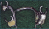
RPD Max & Mand Frameworks

Properties of the major connector
rigidity
not impinge on soft tissue
not placed on movable tissue
cross arch stability
connects all components
resists flexure
provide a means for placement of one or more denture bases
makes sure that parts are unified and effective
Mandibular MC: Lingual bar, lingual plate
Sublingual bar, lingual bar with cingulum bar, cingular bar
labial bar

Lingual Bar
above the movable tissue in the floor of the mouth
below the gingival margin
half pear shaped: superior margin is tapered and the inferior is rounded 4mm below

Mandibular Connector
height of the floor of the mouth measurement:
tongue lightly touching vermillion border of the upper lip - raises the floow of the mouth
measurement can be transferred to the case - indicates location of the inferior border of major connector - 8 mm from free gingival margin to the elevated floor of the mouth

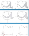
Lingual plate
lingual frenum is too high
space for the lingual bar is limited - the superior border of the bar would be too close to the gingival tissue
plate permits the inferior border to be placed superiorly - avoiding tongue or gingival irritation
half-pear shape as w/ the bar & thin as technically possible incisally & follow the contour of the teeth and embrasures
bracing & stabilizing effect for periodontally challenged mandibular anterior teeth

Lingual Bar vs. Lingual Plate
Bar: superior border of the bar 4 mm below gingival margin of anterior teeth.
Inferior border of bar should not impinge on the movable tissue of the floor of the mouth
Plate: if inferior border of the bar is impinging on the tissue fo the floor of the mouth
if mandible tori is present
Maxillary Major Connector
In contrast to the mandible, the maxilla has no movable tissue as in the floor of the mouth
tissue covering the palate has firm submucosal connective tissue and good blood supply
Variety of maxillary major connectors:
single palatal bar
single palaral strap
U-shaped
anterior-posterior bar
anterior-posterior strap
full palatal

Location of the Major Connector
Maxillary: superior border located at least 6mm below free gingival margin
8mm in width

Single palatal strap:
Kennedy Class III
short edentulous areas
needs additional bulk in thickness
interfere with speech 8 mm in width

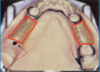
Anterior-posterior strap
any kennedy class
flat min of 8mm in width
max torus interferes in placement
weak perio support
flexure is non-existent
anterior strap can be extended to support an anterior edentulous area

Palatal Plate
Kennedy Class I
anterior edentulous area
can be uniformly thin
reproduced the anatomic contour
more acceptable to the tongue

U-shaped
used in particular in case of torus palatinus
patient that has had u-shaped before
interferes with speech
less rigid therefore made thicker

Single Palatal Bar
less than 8 mm in width
made thicker for rigidity
poor patient acceptance
Anterior-posterior bars
not used frequently
requires bulk for strength - interferes w/ speech

Indications for Max MC
weak perio support of the remaining teeth-more of the palate uncovered: A-P strap
long span distal extension, need more rigidity: A-P strap
anterior teeth to be replaced: A-P strap, u-shaped, or complete palate
torus present: u-shaped
modifying factors: number & location remaining teeth, perio support, type of opposing occlution
Minor connectors
primary function: connecting link between the major connector and the other components of the prosthesis (RPD)
distributes forces to the teeth and ridge tissues
rigid, at same time min bulk, conform to the interdental embrasure

Types of minor connectors
clasps assemblies
indirect retainers & auxiliary rests
denture bases
bar-type clasps

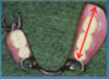
Rests
forces that are applied to an RPD must be transferred to the supporting teeth and tissue
rests are the components of an RPD that transfer the forces down the long axis of the abutment teeth
the prepared areas of the abutment teeth in which the rest fits is called the rest seat
Primary function of the Rests
maintains components in planned position
maintains established occlusal relationships prevents settling of the RPD
prevents impingement of soft tissue
directs and distributes occlusal (vertical) loads to long axis of abutment teeth
Types of Rests
occlusal rests - occlusal surfaces of posterior teeth
lingual or cingulum - lingual surfaces of anterior teeth
incisal - incisal edges of anterior teeth