Optical Fibres Flashcards
Features of ITU G.652 Single Mode Fibre
0.2db/km Loss @ 1550nm
Mode Diameter 9-10um
Cut Off Wavelength 1000 to 1280nm
Dispersion 0.17ps/(nm*km) @ 1550nm
Bend Loss @ 1550nm <1db for 100 turns at 75nm radius

Two General Steps In Fabrication Of Optical Fibres?
Preform Fabrication, then
Fibre Drawing
What Are the Primary Considerations In Preform Fabrication?
Low Water Content
High Purity
Precise Dimensions
Refractive Index Control.
What is the main method of preform Fabrication?
Silica gas Deposition
Other than silica gas deposition what other methods can be used for preform fabrication?
Liquid Melting,
Rod in Tube used for short device
Casing.
What are the three types of silica gas deposition?
Vapour Axial Deposition
Outside Vapour depostion
Modified Chemical Vapour Deposition
Describe Basic Chemistry of Silica Deposition (gas phase)
Volatile Halide Compounds formed from distillation of carrier gas through liquid halide are doped.
The mixture is Oxidised,
Deposition Occurs on to Substrate, Dopant Conc can be varied for graded index and step Index
Features of Vapour Axial Deposition (VAD)
Used Commonly for Transmission Fibres
Low Loss
Suitable for Multimode and Single mode Fibres
Large Preform so Suitable for Long Fibres
High-Speed Deposition
Continuos Production Possible
Describe VAD deposition
This is a process that uses end-on deposition onto a rotating fused silica target. The vaporized constituent substances are injected from burners and react to form silica soot via flame hydrolysis.
Silica soot is much less dense than silica and is deposited onto the end of the target in an axial direction to form a solid preform in a shape similar to a ball.
As the preform grows it is pulled upwards at a rate dependent on the growth rate.
It is first dehydrated using chloride and then sintered into a solid preform.

Important features of the VAD process
Soot is deposited as particles with a typical diameter of < 0.1um.
Soot is much less dense than silica by around a factor of ten,
Dopants are often not formed as particles in the flame, they condense onto silica particles
Particles impact the preform due to the thermophoretic force
Consolidation is the process of sintering soot into a solid
Consolidation can be performed online or offline in a furnace.
The atmosphere is controlled during consolidation, chlorine may be used to remove water via HCL and oxygen.
Define sintering
The process of compacting and forming a solid mass of a substance via pressure or heat, without heating to the point of liquefication.
Define the thermophoretic force
Thermophoresis is the force generated due to the temperature gradient between the hot gas and cold wall, in this case preform.
What diameter are preforms to be drawn to
100mm dia preforms are drawn to around 1/8mm dia fibres
Features of OVD
Batch Process, preform can be drawn for several kilometre fibres, suitable for core or claaing, Allows fine control of graded index for high bandwidth products, purity dependent of purity of feeding materials and OH impurity from flame.
In addition the mandrel when removed may lead to cracks in surface of the perform.
Process of MCVD?
- Pure oxygen and halide vapour flows though a high purity silica tube.
- A heat source (usually a H2/O2flame) heats a small section of the tube.
- In the hot region the halides are oxidised.
- Thermophoresis∗drives the silica particles to adhere to the tube.
- As the heat source passes over the soot it is consolidated.
- Multiple layers are deposited, each with carefully controlled dopant concentration giving accurate control of refractive index profile.
- The tube is collapsed to a solid rod by heating to more than 2000°C, such that the surface tension overcomes the viscosity and the tube collapses.

Features of MCVD
- Unlike VAD or OVD the process is conducted within a tube in the absence of hydrogen–thus allowing very low OH contamination without the lengthy drying
- Very versatile process giving highly precise control of the refractive index profile
- Widely used for speciality fibre production.

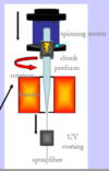
Describe Fibre Drawing
• ‘Drop’ to start the process
• Capstan speed controlled in a feedback loop from diameter gauge
• Fibre loss and strength can be affected by drawing
– Diameter fluctuation
• Draw temperature & tension
• Purge gas turbulence
– Flaws
• Contamination
• Damage
– Poor coating
• Coating –physical and chemical protection.
– Optical properties key for double-clad fibres
– Acrylate -UV crosslinked, high or low index
– Silicone –thermally cured, low index
• Can spin preform to reduce birefringence (up to 2000 rpm)

Concerns when Fibre Drawing
You must be mindful of potential contamination of the fibre, and in turn, introduce some losses.

Define free space velocity
Velocity of light in free space:
𝑐 =𝑓𝜆0 =1/ sqrt(𝜇0𝜖0) ≈ 3×10⁸𝑚/𝑠
Define refractive index
𝑛 = sqrt(𝜖𝑟)
(remember that permittivity is a strong function of frequency)
Define Phase Velocity
The velocity of light in a medium of refractive index n: 𝑣𝑝=𝑓𝜆=1/sqrt(𝜇0𝜖0𝜖𝑟)
Define Angular Frequency
Angular frequency: ω (radians/second)
Define Wavenumber
Wavenumber: 𝑘=2𝜋/𝜆=𝜔 *sqrt(𝜇0𝜖0𝜖𝑟)
(if free space then εr= 1 and we use k0 and λ0)
Equation For Plane Wave
A plane wave can be expressed in the form
𝑬=𝑨𝑒𝑗𝜔t−𝑘z


