ATA 32: Landing Gear Flashcards
The landing gear is not down on approach (below 750 R.A) and full flap is selected. Warning lights appear and a continuous repetitive chime sounds. The chime can be cancelled by:
(a) Pressing Master Caution push button
(b) Pressing Master Warning push button
(c) Pressing the EMERG CANCEL push button
(c) Pressing the EMERG CANCEL push button
The disconnect button on the Captain’s steering hand wheel when depressed:
(a) Allows steering authority by rudder pedals
(b) Allows steering authority by Captain’s rudder pedals
(c) Disconnects the rudder pedal input to the Brake and Steering Control Unit (BSCU)
(c) Disconnects the rudder pedal input to the Brake and Steering Control Unit (BSCU)
LDGGR_01
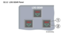
Understand the control functions and indications on the LND GEAR panel.
1. UNLK Lights
- Illuminates red if there is a __________ between the selected gear position and the actual position of the gear.
VOL II., 32.3.2-6

LDGGR_01
Understand the control functions and indications on the LND GEAR panel.
1. UNLK Lights
- Illuminates red if there is a disagreement between the selected gear position and the actual position of the gear.
VOL II., 32.3.2-6

LDGGR_01
Understand the control functions and indications on the LND GEAR panel.
2. Green Triangles
- Illuminates green when LGCIU 1 (LANDING GEAR CONTROL INTERFACE UNIT) detects that the respective gear is _____________\_
VOL II., 32.3.2-6
LDGGR_01
Understand the control functions and indications on the LND GEAR panel.
2. Green Triangles
- Illuminates green when LGCIU 1 (LANDING GEAR CONTROL INTERFACE UNIT) detects that the respective gear is downlocked.
VOL II., 32.3.2-6

LDGGR_01
Understand the control functions and indications on the LND GEAR panel.
3. Landing Gear Lever
- UP - The landing gear are selected up.
- DOWN - The landing gear are selected down.
- Red Arrow
- Illuminates red if the gear are not ________ and either:
- The aircraft is below [_____] ft. RA and flaps ________,
- or
- The aircraft is below [_____] RA with flaps __ or __, and engines not at ________ power,
- or
- Both ________ altimeters are failed and the flaps are selected to position __, __, or ______.
- Illuminates red if the gear are not ________ and either:
LDGGR_01
Understand the control functions and indications on the LND GEAR panel.
3. Landing Gear Lever
- UP - The landing gear are selected up.
- DOWN - The landing gear are selected down.
- Red Arrow
- Illuminates red if the gear are not downlocked and either:
- The aircraft is below [750] ft. RA and flaps full,
- or
- The aircraft is below [750] RA with flaps 2 or 3, and engines not at TOGA power,
- or
- Both radio altimeters are failed and the flaps are selected to position 2, 3, or FULL.
- Illuminates red if the gear are not downlocked and either:
VOL II., 32.3.2-6

LDGGR_01
Understand the control functions and indications on the LND GEAR panel.
4. LDG GEAR GRVTY EXTN Selector
• OFF - Landing gear gravity extension is not _______
• DOWN:
- Isolates the landing gear from the ________ hydraulic system,
- ________ unlocks the landing gear doors,
- and allows the landing gear to extend by________.
- ______ ______ is also lost.
• RESET (momentary action) - Resets the landing gear system.
If the malfunction that required the gravity extension is no longer present, selecting ________:
- ________ the gear doors
- Recovers normal gear ______ and ______
- Recovers ______ ______
• Red Selector Guards -
- Prevent inadvertent ________of the LDG GEAR GRVTY EXTN selector.
- Hinged so they can be moved if landing gear gravity ________is desired.
VOL II., 32.3.2-6

LDGGR_01
Understand the control functions and indications on the LND GEAR panel.
4. LDG GEAR GRVTY EXTN Selector
• OFF - Landing gear gravity extension is not selected.
• DOWN:
- Isolates the landing gear from the green hydraulic system,
- electrically unlocks the landing gear doors,
- and allows the landing gear to extend by gravity.
- Nosewheel steering is also lost.
• RESET (momentary action) - Resets the landing gear system.
If the malfunction that required the gravity extension is no longer present, selecting RESET:
- Closes the gear doors
- Recovers normal gear extension and retraction
- Recovers nosewheel steering
• Red Selector Guards -
- Prevent inadvertent movement of the LDG GEAR GRVTY EXTN selector.
- Hinged so they can be moved if landing gear gravity extension is desired.
VOL II., 32.3.2-6

LDGGR_01
Understand the control functions and indications on the LND GEAR panel.
5. DECEL Lights
- • Illuminates green:
- if the respective autobrake setting is ________
- and actual aircraft deceleration reaches [____%] of the TARGET rate for LO or MED or a FIXED rate for MAX.
- • ON Lights - Illuminates ________ when the respective setting has been ________
VOL II., 32.3.2-6
LDGGR_01
Understand the control functions and indications on the LND GEAR panel.
5. DECEL Lights
- • Illuminates green:
- if the respective autobrake setting is active
- and actual aircraft deceleration reaches [80%] of the target rate for LO or MED or a fixed rate for MAX.
- • ON Lights - Illuminates blue when the respective setting has been armed.
VOL II., 32.3.2-6

LDGGR_01
Understand the control functions and indications on the LND GEAR panel.
- A/SKID & N/W STRG Switch
- ON - Both channels of the ______ ______ ______ ______ (BSCU) are available.
- OFF - Both channels of the BSCU are off. As a result:
- ________ braking is lost.
- ________ is lost.
- ______ ______ is lost.
- ________ lost
VOL II., 32.3.2-6

LDGGR_01
Understand the control functions and indications on the LND GEAR panel.
- A/SKID & N/W STRG Switch
- ON - Both channels of the Brake Steering Control Unit (BSCU) are available.
- OFF - Both channels of the BSCU are off. As a result:
- Normal braking is lost.
- Antiskid is lost.
- Nosewheel steering is lost.
- Autobrakes lost
VOL II., 32.3.2-6

LDGGR_01
Understand the control functions and indications on the LND GEAR panel.
7. BRAKES Indicator
- Provides indications of ________ hydraulic system brake pressure if ________ braking is unavailable or the ________ brake is set.
- The top of the green arcs indicate the ________ recommended brake pressure of [________] psi to prevent locking the brakes if the ________ is inoperative.
VOL II., 32.3.2-6

LDGGR_01
Understand the control functions and indications on the LND GEAR panel.
7. BRAKES Indicator
- Provides indications of blue hydraulic system brake pressure if normal braking is unavailable or the parking brake is set.
- The top of the green arcs indicate the maximum recommended brake pressure of [1000] psi to prevent locking the brakes if the antiskid is inoperative.
VOL II., 32.3.2-6

LDGGR_01
Understand the control functions and indications on the LND GEAR panel.
8. ACCU PRESS Indicator
- Provides indications of remaining ________ hydraulic accumulator pressure.
- Normal accumulator pressure is indicated by the ________ band.
- If the indicator is in the amber band, accumulator pressure is ______ ______.
VOL II., 32.3.2-6

LDGGR_01
Understand the control functions and indications on the LND GEAR panel.
8. ACCU PRESS Indicator
- Provides indications of remaining blue hydraulic accumulator pressure.
- Normal accumulator pressure is indicated by the green band.
- If the indicator is in the amber band, accumulator pressure is critically low.
VOL II., 32.3.2-6

LDGGR_02
Understand the control functions of the Parking Brake Handle.
Parking Brake Handle
- ON - Pull up while turning ________ to engage parking brake.
- ______ and ______ braking systems are deactivated and braking pressure is applied by the ________ system or ______ ______.
- PARK BRK memo message is displayed.
- OFF - Parking brake is released.
VOL II., 32.3.2-6

LDGGR_02
Understand the control functions of the Parking Brake Handle.
Parking Brake Handle
- ON - Pull up while turning clockwise to engage parking brake.
- Normal and alternate braking systems are deactivated and braking pressure is applied by the blue system or brake accumulator.
- PARK BRK memo message is displayed.
- OFF - Parking brake is released.
VOL II., 32.3.2-6
LDGGR_03
Understand the control functions of the Steering Handwheels.
- Steering handwheels are located on each pilot’s outboard side console.
- The handwheels command a nosewheel angle that corresponds to the angles printed on their base.
- Full authority is [____°] L/R and gradually ________ as ground speed increases.
- As the angle of the handwheel increases, additional steering inputs result in a ______ ______ in nosewheel angle
- (i.e., nosewheel steering using the handwheels is ______ ______ as the angle of the handwheel______).
VOL II., 32.1.7.1-4
LDGGR_03
Understand the control functions of the Steering Handwheels.
- Steering handwheels are located on each pilot’s outboard side console.
- The handwheels command a nosewheel angle that corresponds to the angles printed on their base.
- Full authority is [72°] L/R and gradually decreases as ground speed increases.
- As the angle of the handwheel increases, additional steering inputs result in a larger change in nosewheel angle
- (i.e., nosewheel steering using the handwheels is more sensitive as the angle of the handwheel increases).
VOL II., 32.1.7.1-4
LDGGR_03
Understand the control functions of the Steering Handwheels.
- The handwheels are not ____________
- Inputs made with one handwheel do not affect the position of the other handwheel.
- If an input is made with both handwheels simultaneously, the combined input is _______ by the _______ up to the _______ authority for one handwheel.
VOL II., 32.1.7.1-4
LDGGR_03
Understand the control functions of the Steering Handwheels.
- The handwheels are not interconnected.
- Inputs made with one handwheel do not affect the position of the other handwheel.
- If an input is made with both handwheels simultaneously, the combined input is summed by the BSCU up to the maximum authority for one handwheel.
VOL II., 32.1.7.1-4
LDGGR_03
Understand the control functions of the Steering Handwheels.
The rudder pedals can be _______ from nosewheel steering (e.g., for checking rudder travel during taxi):
- by pushing and holding the _____ _____ pushbutton in the center of the steering handwheel.
- Releasing the pushbutton _______ steering control to the rudder pedals.
VOL II., 32.1.7.1-4

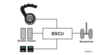
LDGGR_03
Understand the control functions of the Steering Handwheels.
The rudder pedals can be disconnected from nosewheel steering (e.g., for checking rudder travel during taxi):
- by pushing and holding the PEDALS DISC pushbutton in the center of the steering handwheel.
- Releasing the pushbutton returns steering control to the rudder pedals.
VOL II., 32.1.7.1-4
LDGGR_04
Discuss normal and abnormal indications on the ECAM WHEEL page.
1. Spoiler Indications
- Indicates the __________ of the spoilers.
VOL II., 32.3.9

LDGGR_04
Discuss normal and abnormal indications on the ECAM WHEEL page.
1. Spoiler Indications
- Indicates the position of the spoilers.
VOL II., 32.3.9

LDGGR_04
Discuss normal and abnormal indications on the ECAM WHEEL page.
2. Gear Door Indications
The door indications provide a graphical representation of the gear door position:
- locked up (_______),
- in transit or open (_______),
An _______ indication appears above the gear door if the uplock is engaged when the landing gear is ______._
VOL II., 32.3.9

LDGGR_04
Discuss normal and abnormal indications on the ECAM WHEEL page.
2. Gear Door Indications
The door indications provide a graphical representation of the gear door position:
- locked up (green),
- in transit or open (amber),
An UPLOCK indication appears above the gear door if the uplock is engaged when the landing gear is DOWNLOCKED.
VOL II., 32.3.9

LDGGR_04
Discuss normal and abnormal indications on the ECAM WHEEL page.
3. Landing Gear Indications
- Two _______ indicate the landing gear position.
- The left triangle from_______,
- the right triangle from _______.
- _______ Triangle - Landing gear downlocked
- Red Triangle - Landing gear __ _____
- No symbol - Landing gear_____
- XX (amber) - _____ _____
VOL II., 32.3.9

LDGGR_04
Discuss normal and abnormal indications on the ECAM WHEEL page.
3. Landing Gear Indications
- Two triangles indicate the landing gear position.
- The left triangle from LGCIU 1,
- the right triangle from LGCIU 2.
- Green Triangle - Landing gear downlocked
- Red Triangle - Landing gear in transit
- No symbol - Landing gear uplocked
- XX (amber) - LGCIU failure
VOL II., 32.3.9

LDGGR_04
Discuss normal and abnormal indications on the ECAM WHEEL page.
4. Brake Temperatures
Indicates brake temperature on the respective wheel.
- Normally ______,_
- minimum display temperature [____°]C.
- Amber at ____°_ C and above.
- An arc appears _______ the wheel with the _______ brakes (min temp [__\_°C]),
- if that temperature is greater than _____°, the arc is _______
VOL II., 32.3.9

LDGGR_04
Discuss normal and abnormal indications on the ECAM WHEEL page.
4. Brake Temperatures
Indicates brake temperature on the respective wheel.
- Normally green,
- minimum display temperature [0°]C.
- Amber at 300° C and above.
- An arc appears above the wheel with the hottest brakes (min temp [100°C]),
- if that temperature is greater than 300°, the arc is amber
VOL II., 32.3.9

LDGGR_04
Discuss normal and abnormal indications on the ECAM WHEEL page.
5. Tire Pressures
- Deactived.
6. Messages
- _____ _____ (amber) - Normal braking is lost
- ANTI-SKID (amber) - _______ function is lost
- AUTO BRK
- Green - Auto brake is _______, followed by selected setting LO, MED, or MAX
- Amber - _______ is lost
VOL II., 32.3.9

LDGGR_04
Discuss normal and abnormal indications on the ECAM WHEEL page.
5. Tire Pressures
- Deactived.
6. Messages
- NORM BRK (amber) - Normal braking is lost
- ANTI-SKID (amber) - Anti-skid function is lost
- AUTO BRK
- Green - Auto brake is armed, followed by selected setting LO, MED, or MAX
- Amber - Auto brake is lost
VOL II., 32.3.9

LDGGR_04
Discuss normal and abnormal indications on the ECAM WHEEL page.
7. Antiskid Indications
Vertical bars indicate the anti-skid system.
The “R” is permanently displayed to indicate the bars refer to the brake ______._
- Green - Brakes are _____: (in flight with _____ _____, or released due to _______ activation during braking)
- Amber - _______ brake pressure exists when a release command is given, or brake release _______ is detected.
VOL II., 32.3.9

LDGGR_04
Discuss normal and abnormal indications on the ECAM WHEEL page.
7. Antiskid Indications
Vertical bars indicate the anti-skid system.
The “R” is permanently displayed to indicate the bars refer to the brake release.
- Green - Brakes are released: (in flight with gear extended, or released due to antiskid activation during braking)
- Amber - Residual brake pressure exists when a release command is given, or brake release fault is detected.
VOL II., 32.3.9

LDGGR_04
Discuss normal and abnormal indications on the ECAM WHEEL page.
8. N/W STRG
- N/W STRG appears in amber if nosewheel steering is lost due to:
- Failure detected by _______
- A/SKID & N/W STRG switch _______
- Failure of both _______ channels
VOL II., 32.3.9

LDGGR_04
Discuss normal and abnormal indications on the ECAM WHEEL page.
8. N/W STRG
- N/W STRG appears in amber if nosewheel steering is lost due to:
- Failure detected by BSCU
- A/SKID & N/W STRG switch OFF
- Failure of both BSCU channels
VOL II., 32.3.9

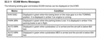
LDGGR_05
Discuss the meaning of the ECAM memos as they relate to landing gear/brakes system.
N/W DISC
- Displayed in green when the towing lever on the nose gear is in the _______ position.
- It is displayed in _______ if an engine is running.
VOL II., 32.3.11

LDGGR_05
Discuss the meaning of the ECAM memos as they relate to landing gear/brakes system.
N/W DISC
- Displayed in green when the towing lever on the nose gear is in the TOWING position.
- It is displayed in amber if an engine is running.
VOL II., 32.3.11

LDGGR_05
Discuss the meaning of the ECAM memos as they relate to landing gear/brakes system.
PARK BRK
- Displayed in green when the parking brake is set.
- It is displayed in amber if the parking brake is set in _______
VOL II., 32.3.11
LDGGR_05
Discuss the meaning of the ECAM memos as they relate to landing gear/brakes system.
PARK BRK
- Displayed in green when the parking brake is set.
- It is displayed in amber if the parking brake is set in flight.
VOL II., 32.3.11

LDGGR_05
Discuss the meaning of the ECAM memos as they relate to landing gear/brakes system.
AUTO BRK LO
- Displayed in green when autobrakes LO is armed and the aircraft is below [_____] feet.
VOL II., 32.3.11

LDGGR_05
Discuss the meaning of the ECAM memos as they relate to landing gear/brakes system.
AUTO BRK LO
- Displayed in green when autobrakes LO is armed and the aircraft is below [800] feet.
VOL II., 32.3.11


