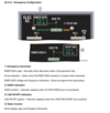
ATA 24: Electrical Flashcards

1
Q

The Main AC generators are ______ ______ each with a nominal output of ______ kVA.

A

Two Main AC generators are engine driven each with a nominal power ouput of 115 kVA.

2
Q

The Auxiliary Power Unit (APU) AC generator
has a nominal power output of ______ kVA.

A

The APU AC generator has a nominal power output of 115 kVA.

3
Q

The Emergency Generator is a ______ ______ ______ ______ (CSM/G) with a nominal power output of ______ kVA.

It is driven by the ______ system.

A

The Emergency Generator is a Constant Speed Motor/Generator (CSM/G) with a nominal power output 8.6 kVA.

Hydraulically driven by the GREEN system

4
Q

The Static Inverter is fed by ______ ______ and operates on the ______ when the ______ is inoperative.

A

The Static Inverter is fed by two batteries and operates on the ground when the CSM/G is inoperative.

5
Q

Describe the Ground Connectors - number and power output.

A

Two ground connectors
with an ouput of 90 kVA each

6
Q

There are ______ main TRU’s (200A), ______ essential TRU (100A) and ______ TRU (100A) dedicated to the ______ ______ or ______ ______ ______.

A

There are two main TRU’s (200 A), one essential TRU (100 A), and one TRU (100 A) dedicated to the APU start or APU battery charging.

7
Q

There are ______ batteries, each with a nominal capacity of 28v.

______ are used in ______ ______ during ______ deployment or when the ______ is not operating.

______ is dedicated to the ______ start.

A

There are three batteries, each with a nominal capacity of 28v.

Two are used in emergency configuration during RAT deployment or when the CSM/G is not operating

One is dedicated to the APU start.

8
Q

Describe the AC Distribution Network

  • Normal configuration: each ____ ____ ____ supplies its _____ AC BUS.
  • AC ESS BUS is normally supplied from ____ ____ __
A
  • Normal configuration: each engine-driven generator supplies its associated AC BUS.
  • AC ESS BUS is normally supplied from AC BUS 1.
9
Q

Describe the DC Distribution Network - Normal Configuration

A

-The normal DC system is split into two networks: DC BUS 1 in parallel with DC BAT BUS and DC BUS 2.
- Each DC network is supplied by its own Transformer Rectifier (TR).

10
Q

Describe the DC ESS BUS

The DC ESS BUS is fed by the ___ ___ systematically for better segregation between DC 1 and DC 2.

A

The DC ESS BUS is fed by the ESS TR systematically for better segregation between DC 1 and DC 2.

11
Q

What is the relationship between the batteries and HOT BUS Bar?

A

Two batteries are permanently connected to the two hot busses.

12
Q

What is the third battery used for?

A

The third battery is dedicated to APU starting.

13
Q

What is the Battery Charge Limiter (BCL) used for?

A

The Battery Charge Limiter (BCL) connect two batteries to the DC BAT BUS.

14
Q

Describe what happens when a generator fails

A

If one generator fails, another will automatically take over.
If APU is operative, APU generator will take over.
If APU generator is not available, the other engine generator will take over.

15
Q

What happens with a total loss of all main generators (engines still running)?

A

The emergency generator delivers 8.6 kVA of power and the GREEN hydraulic system is still powered by engine-driven pumps.

16
Q

What happens in the case of total generator failure due to all-engines loss?

A
  • The emergency generator delivers 3.5 kVA via the GREEN hydraulic system.
  • It is powered by the RAT (otherwise the engine pump(s) if at least one engine is running).
  • Batteries take over when slats are extended.
17
Q

What happens with a single TR failure?

A

If one TR fails, the other will automatically take over its corresponding DC network via DC BAT BUS.

18
Q

What happens with a double TR failure? (Two possible scenarios)

A
  1. TR 1 and 2: DC BUS 1 and DC BUS 2 are lost.
  2. TR 1 (or 2) and ESS TR: The remaining TR supplies DC BUS 1 + 2 and DC BAT BUS; the DC ESS BUS is lost.
19
Q

How are the circuit breakers monitored?

A

By the CBMU (Circuit Breaker Monitoring Units) and a C/B page on the ECAM.

20
Q

If external power is available and is within the power criteria for aircraft use:
(a) It will automatically close the bus tie contactor’s when connected by the ground crew
(b) The GREEN avail light will illuminate on the EXT PWR pb
(c) The bus tie Pb illuminates

A

(b) The GREEN avail light will illuminate on the EXT PWR pb

21
Q

If during a normal flight, the BUS TIE Pb was depressed to off, what effect would this have on power to the busses?

(a) None
(b) All power would be lost and the batteries would power the aircraft until the RAT was up to speed
(c) AC ESS Bus will be lost and ALTN light on AC ESS FEED switch will illuminate

A

(a) None

22
Q

If both engine generators are powering the system, and one subsequently fails, are any
busses unpowered?

(a) No, but some loads are shed in the galleys
(b) Only the AC ess. Shed bus
(c) Yes, those associated with the failed generator

A

(a) No, but some loads are shed in the galleys

23
Q

What would cause the galley fault light to illuminate?

(a) When the flight attendants have all the coffee makers and ovens on at once
(b) When the main galley has shed
(c) When an overload is detected and auto shedding is not performed

A

(c) When an overload is detected and auto shedding is not performed

24
Q

What is the function of APU GEN pb located on the overhead electrical panel?

(a) When on it connects APU generator to the electrical system when engines are running
(b) When selected to off the APU generator field is de-energised and if connected to the electrical system, disconnects
(c) Both A and B are correct

A

(b) When selected to off the APU generator field is de-energised and if connected to the electrical system, disconnects

25
If the normal source of power for the ESS AC Bus is lost, does another source of power automatically power the bus? (a) Yes, only if NORMAL was selected on the AC ESS FEED Pb (b) Yes, only if ALTN was selected on the AC ESS FEED Pb (c) No, this is an action that must be accomplished by the crew
(a) Yes, only if NORMAL was selected on the AC ESS FEED Pb
26
Whilst the RAT is deployed in an emergency, the static inverter supplies the: (a) AC ESS BUS and AC Ess Grnd (b) AC ESS BUS and AC Ess Shed Bus (c) AC ESS BUS only
(c) AC ESS BUS only
27
Electrical Contractor Management Unit (ECMU) function is: a. control of AC and DC bus ties b.     TR contractors monitoring c.      automatic management and monitoring
c.      automatic management and monitoring
28
Loss of one generator or TR: a. results in the loss of the corresponding AC or DC bus b.     has no effect on flight management c.      requires to have the APU generator operational
b.     has no effect on flight management
29
The minimum number of generators required to supply all the network (in a non-overload condition) is a. one engine generator b.     one engine generator and the EMER generator c.      two generators
a. one engine generator
30
The emergency generator is powered by: a. a Ram Air Turbine b.     the Static Inverter c.      the green hydraulic system when pressurized by engine 1 or 2 driven hydraulic pump or by Ram Air Turbine
c.      the green hydraulic system when pressurized by engine 1 or 2 driven hydraulic pump or by Ram Air Turbine
31
An engine generator is driven: a. at a ratio of 5:1 to engine speed b.     direct from the accessory gear box c.      by an Integrated Drive Generator (IDG)
c.      by an Integrated Drive Generator (IDG)
32
Each engine generator supplies power to: a. its assigned AC BUS in normal operation b.     the opposite side AC BUS in normal operation c.      only its assigned BUS in all cases
a. its assigned AC BUS in normal operation
33
The APU battery: a. is dedicated to APU start only b.     may be used for Engine Start when the APU is not available c.      can be used as a backup for Battery One or Battery Two
a. is dedicated to APU start only
34
Normally which AC BUS supplies the ESS TR? a. AC BUS 1 b.  AC BUS 2 c. AC ESS BUS
a. AC BUS 1
35
When the Battery selector is in the #2 position, which of the following is true? a. BAT 2 has been selected to start the APU b.     BAT 2 voltage can now be read in the voltage indicator window c.      APU BAT voltage can now be read in the voltage indicator window
b.     BAT 2 voltage can now be read in the voltage indicator window
36
In flight, APU not running, an engine generator has failed, which source is supplying the the corresponding AC BUS? a. the Static Inverter b.     the AC BUS is lost c.      the other side engine generator
c.      the other side engine generator
37
Two Electrical Contactor Management Unit (ECMU) provide: a. control of TR contactors b.     AC and DC contactors control and monitoring except for TR contractors c.      AC and DC contactors control and monitoring except for TRs which have their own control, gallery shedding and no break power transfer
c.      AC and DC contactors control and monitoring except for TRs which have their own control, gallery shedding and no break power transfer
38
The ESS TR s normally supplied by which BUS? a. AC ESS BUS b.     AC BUS 1 c.      AC BUS 2
b.     AC BUS 1
39
When TR 1 is lost, due to unpowered AC BUS 1: a. there is no degradation in the capability of the DC system b.     the APU BAT BUS is discharging at a rate of 2 amperes c. the Static Inverter is being powered because TR 1 is not powered
a. there is no degradation in the capability of the DC system
40
121. When the C/B ECAM page shows NORMAL in green, it indicates: a. there are no C/Bs tripped or pulled b.     electric supply to C/Bs is normal c.      no fault detected in the Electronic Equipment Bay
a. there are no C/Bs tripped or pulled
41
122. The last C/B tripped is displayed (ECAM C/B page): a.     on top of the tripped C/B list b.     on the last tripped C/B list c.      not shown
a.     on top of the tripped C/B list
42
123. When the C/B ECAM page shows NOT AVAIL in amber, it indicates: a.     the C/B ECAM page is not selectable b.     requested C/Bs are not monitored by the CBMU c.      data from the CBMU are not monitored by the CBMU
c.      data from the CBMU are not monitored by the CBMU
43
124. During EMER GEN automatic start up sequence: a. the MAN ON pb must be pushed to extinguish red FAULT light on the EMER ELEC CTRL PANEL b.     it is not recommended to push the MAN ON pb to confirm EMER ELEC config on the EMER ELEC PANEL c.      the RED FAULT light on EMER ELEC PANEL will remain ON until the EMER GEN reaches its nominal output
c.      the RED FAULT light on EMER ELEC PANEL will remain ON until the EMER GEN reaches its nominal output
44
125. The EMER GEN is being powered by a hydraulic system pressurized by an engine driven hydraulic pump. Pressing the LAND RECOVERY push button switch will: a. operate when the gear is extended b.     normally recover the AC and DC LAND RECOVERY BUSES and the DC SHED LAND RECOVERY BUS. This will power some components for approach and landing c.      energize the landing gear
b.     normally recover the AC and DC LAND RECOVERY BUSES and the DC SHED LAND RECOVERY BUS. This will power some components for approach and landing
45
126. The main function of the MAINT BUS SWITCH is: a. to power the AC and DC systems when the aircraft is on the ground b.     to allow selected ground services equipment to be powered without powering the entire aircraft electrical system. c.      to allow EXT power to supply AC and DC essential busses and their respective shed buses
b.     to allow selected ground services equipment to be powered without powering the entire aircraft electrical system.
46
127. When the MAINT BUS SWITCH is ON: a.     the electric network supply is limited to Ground Service items b.     the DC busses are powered only c.      it is for the purpose of operating the cargo door only
a.     the electric network supply is limited to Ground Service items
47
128. The MAINT BUS SWITCH is located: a. on the overhead systems panel in the cockpit b.     overhead, before entry of the cockpit door c.      on the Purser’s Control Panel in the FWD cabin
b.     overhead, before entry of the cockpit door
48
When ECAM shows ELEC ECMU 1 FAULT amber message (ECMU = Electrical Contractor Management Unit): a. ECMU 1 controls Generator Line Contractor (GLC) 2; you should reset generator 2 b.     ECMU 1 controls GLC 1 and you should not reset the corresponding generator c.      ECMU 1 controls GLC 1 and you should try to reset the corresponding generator
b.     ECMU 1 controls GLC 1 and you should not reset the corresponding generator
49
130. A MASTER CAUTION light with a single chime and the following ECAM memo ELEC GEN 2 FAULT illuminate amber, this means that: a. an ECMU fault b.     a TR overload c.      a generator fault
c.      a generator fault
50
131. The FAULT light of the GALLEY pb switch will illuminate amber when: a. galley circuits are shed b.     an overload is detected and the automatic shedding is not operating c. the automatic shedding, manual override and overload detection are not operating
b.     an overload is detected and the automatic shedding is not operating
51
ECAM message ELEC BAT 1 FAULT is shown on the ECAM. The fault was triggered because: a. charging current increasing at an abnormal rate b.     abnormal voltage c.      the BAT 1 pb is set to OFF
a. charging current increasing at an abnormal rate
52
ECAM message ELEC DC BUS 2 FAULT means: a. a faulty TR b.     the normal connection between DC BAT BUS and DC BUS 2 has been broken c.      DC BUS 2 is not powered
c.      DC BUS 2 is not powered
53
The IDG switch on the ELEC control panel is used: a. to disconnect the generator b.     to disconnect the generator and open the GCU c.      to disconnect the IDG from the accessory gearbox
c.      to disconnect the IDG from the accessory gear box
54
ELEC\_01 Understand the control functions and indications on the ELEC Panel. **1. BAT Select Switch** Selects the battery to display in the battery voltage _**\_\_\_\_\_\_**_ display. V2 24.3.2
ELEC\_01 Understand the control functions and indications on the ELEC Panel. **1. BAT Select Switch** Selects the battery to display in the battery voltage **_LCD_** display. V2 24.3.2
55
ELEC\_01 Understand the control functions and indications on the ELEC Panel. **2. Battery Voltage LCD Display** * Displays _**\_\_\_\_\_\_**_ of the battery selected with the **\_\_\_\_\_\_ \_\_\_\_\_\_** switch. V2 24.3.2
ELEC\_01 Understand the control functions and indications on the ELEC Panel. **2. Battery Voltage LCD Display** * Displays **_voltage_** of the battery selected with the **_BAT select_** switch. V2 24.3.2
56
ELEC\_01 Understand the control functions and indications on the ELEC Panel. **3. BAT 1/2 pbs** Controls the operation of the respective **\_\_\_\_\_\_ ______ \_\_\_\_\_\_** (_**\_\_\_\_\_\_**_). * **On (lights out**) - The BCL controls the connection of the battery to the _**\_\_\_\_\_\_**_ BAT bus. * During ground operations, batteries are automatically _**\_\_\_\_\_\_**_ when battery voltage drops below [_**\_\_\_\_\_\_**_] V. * **OFF** - The BCL is not _**\_\_\_\_\_\_**_ and the battery is not _**\_\_\_\_\_\_**_ to the **\_\_ \_\_\_** bus (except in- flight in the **\_\_\_\_\_\_ \_\_\_\_\_** configuration). * OFF illuminates _**\_\_\_\_\_\_**_ if the **\_\_\_ \_\_\_\_** BUS is powered (power source for the light). * **• FAULT** - Illuminates amber when the charging current for the corresponding battery is **\_\_\_\_ __ \_\_\_\_\_**. * The battery contactor _**\_\_\_\_\_\_**_ automatically. V2 24.3.2
ELEC\_01 Understand the control functions and indications on the ELEC Panel. **3. BAT 1/2 pbs** Controls the operation of the respective **_Battery Charge Limiter_** (**_BCL_**). * **On (lights out**) - The BCL controls the connection of the battery to the **_DC BAT_** bus. * During ground operations, batteries are automatically **_disconnected_** when battery voltage drops below [**_23_**] V. * **OFF** - The BCL is not **_operating_** and the battery is not **_connected_** to the **_DC ESS_** bus (except in- flight in the **_emergency electrical_** configuration). * OFF illuminates **_white_** if the **_DC BAT_** BUS is powered (power source for the light). * **• FAULT** - Illuminates amber when the charging current for the corresponding battery is **_out of limits_**. * The battery contactor **_opens_** automatically. V2 24.3.2
57
ELEC\_01 Understand the control functions and indications on the ELEC Panel. **4. APU BAT pb** * Controls the operation of the APU _**\_\_\_\_\_\_**_. * On (lights out) - The APU _**\_\_\_\_\_\_**_ controls the connection of the APU _**\_\_\_\_\_\_**_ to the _**\_\_\_**_ APU bus. * The battery is connected for _**\_\_\_\_\_\_**_ and when the APU\_\_\_\_\_\_ ______ is initiated. V2 24.3.2
ELEC\_01 Understand the control functions and indications on the ELEC Panel. **4. APU BAT pb** * Controls the operation of the APU **_BCL_**. * On (lights out) - The APU **_BCL_** controls the connection of the APU **_battery_** to the **_DC_** APU bus. * The battery is connected for **_charging_** and when the APU **_start sequence_** is initiated. V2 24.3.2
58
ELEC\_01 Understand the control functions and indications on the ELEC Panel. **5. AC ESS FEED pb** * Normal (lights out) - The AC ESS bus is normally supplied by **AC _____ \_\_\_\_\_**. * When _**AC BUS\_\_\_\_\_**_ is lost, the AC ESS bus is automatically supplied by _**AC BUS \_\_\_\_\_**_ * **ALTN** - The AC ESS bus is supplied by _**AC BUS \_\_\_\_\_**_. * FAULT - Illuminates amber if the _**\_\_\_\_\_**_ _____ bus is not supplied. • Note: In case of loss of both main generators, AC ESS bus is supplied by the **\_\_\_\_\_ \_\_\_\_\_** or the **\_\_\_\_\_ \_\_\_\_\_**. V2 24.3.2
ELEC\_01 Understand the control functions and indications on the ELEC Panel. **5. AC ESS FEED pb** * Normal (lights out) - The AC ESS bus is normally supplied by **_AC BUS 1_**. * It is automatically supplied by **_AC BUS 2_** when **_AC BUS 1_** is lost. * ALTN - The AC ESS bus is supplied by **_AC BUS 2_**. * FAULT - Illuminates amber if the **_AC ESS_** bus is not supplied. • Note: In case of loss of both main generators, AC ESS bus is supplied by the **_emergency generator_** or the **_static inverter_**. V2 24.3.2
59
ELEC\_01 Understand the control functions and indications on the ELEC Panel. **6. GALLEY pb** * AUTO - The galley busses are _**\_\_\_\_\_\_**_ powered. * One or more galleys are shed if a _**\_\_\_\_\_\_**_ fails or an _**\_\_\_\_\_\_**_ is detected. * OFF - All _**\_\_\_\_\_\_**_ are shed and the **\_\_\_\_\_\_/\_\_\_\_\_\_** drain mast protection is lost. * OFF then _**\_\_\_\_\_\_**_ will reset _**\_\_\_\_\_\_**_ lost due to overload protection. * FAULT - Illuminates amber if an _**\_\_\_\_\_\_**_ is detected and _**\_\_\_\_\_\_**_ did not occur. V2 24.3.2
ELEC\_01 Understand the control functions and indications on the ELEC Panel. **6. GALLEY pb** * AUTO - The galley busses are **_normally_** powered. * One or more galleys are shed if a **_generator_** fails or an **_overload_** is detected. * OFF - All **_galleys_** are shed and the **_water/waste_** drain mast protection is lost. * OFF then **_AUTO_** will reset **_galleys_** lost due to overload protection. * FAULT - Illuminates amber if an **_overload_** is detected and **_shedding_** did not occur. V2 24.3.2
60
ELEC\_01 Understand the control functions and indications on the ELEC Panel. **7. COMMERCIAL pb** OFF - COMMERCIAL OFF is displayed on the AC ELEC page and the following equipment is shed: * _**\_\_\_\_\_\_**_ * In-flight _**\_\_\_\_\_\_**_ system * _**\_\_\_\_\_\_**_outlets * _**\_\_\_\_\_\_**_**/\_\_\_\_\_\_**drain mast ice protection * **\_\_\_\_\_\_ and \_\_\_\_\_\_** lights * Water _**\_\_\_\_\_\_**_ * Escape slide **\_\_\_\_\_\_ \_\_\_** protection * **\_\_\_\_\_\_ \_\_\_\_\_\_** system V2 24.3.2
ELEC\_01 Understand the control functions and indications on the ELEC Panel. **7. COMMERCIAL pb** OFF - COMMERCIAL OFF is displayed on the AC ELEC page and the following equipment is shed: * **_Galleys_** * In-flight **_entertainment_** system * **_Electrical_** outlets * **_Water/waste_** drain mast ice protection * **_Cabin and lavatory_** lights * Water **_heaters_** * Escape slide **_lock ice_** protection * **_Cargo loading_** system V2 24.3.2
61
ELEC\_01 Understand the control functions and indications on the ELEC Panel. **8. IDG 1/2 pb** * OFF - Disconnects the **\_\_\_\_\_\_** from its drive shaft. It can only be reconnected by _**\_\_\_\_\_\_**_ personnel on the ground. * FAULT - Illuminates amber for: * IDG oil outlet _**\_\_\_\_\_\_**_ too high * IDG oil _**\_\_\_\_\_\_**_ too low * The fault light extinguishes when the _**\_\_\_\_\_\_**_ is disconnected Note: Press the IDG pb until the **\_\_\_\_\_\_ \_\_\_\_\_\_** light comes on but not for more than _**\_\_\_\_\_\_**_ seconds. V2 24.3.2
ELEC\_01 Understand the control functions and indications on the ELEC Panel. **8. IDG 1/2 pb** * OFF - Disconnects the **_IDG_** from its drive shaft. It can only be reconnected by **_maintenance_** personnel on the ground. * FAULT - Illuminates amber for: * IDG oil outlet **_temperatur_**e too high * IDG oil **_pressure_** too low * The fault light extinguishes when the **_IDG_** is disconnected Note: Press the IDG pb until the **_GEN FAULT_** light comes on but not for more than **_3_** seconds. V2 24.3.2
62
ELEC\_01 Understand the control functions and indications on the ELEC Panel. **9. GEN 1/2 pb** * **On** (lights out) - The engine driven generators _**\_\_\_\_\_\_**_ come on line whenever their _**\_\_\_\_\_\_**_ parameters are within limits. * **FAULT** - The pb is _**\_\_\_\_\_\_**_ and the generator is _**\_\_\_\_**_ being driven (e.g., the _**\_\_\_\_\_\_**_ preflight position). * **OFF/R** - The generator field is _**\_\_\_\_\_\_**_, the line contactor is _**\_\_\_\_\_\_**_, and the _**\_\_\_\_\_\_**_ circuit is reset. V2 24.3.2
ELEC\_01 Understand the control functions and indications on the ELEC Panel. **9. GEN 1/2 pb** * **On** (lights out) - The engine driven generators **_automatically_** come on line whenever their **_electrical_** parameters are within limits. * **FAULT** - The pb is **_on_** and the generator is **_not_** being driven (e.g., the **_normal_** preflight position). * **OFF/R** - The generator field is **_de-energized_**, the line contactor is **_opened_**, and the **_fault_** circuit is reset. V2 24.3.2
63
ELEC\_01 Understand the control functions and indications on the ELEC Panel. **10. APU GEN pb** * **On** (lights out) - The APU generator automatically comes **\_\_ \_\_\_\_** whenever the electrical parameters are within _**\_\_\_\_\_\_**_ and a **\_\_\_\_\_\_ \_\_\_\_\_\_** power source is not already **\_\_ \_\_\_\_**. * **FAULT** - The pb is _**\_\_\_**_ and the generator is not being _**\_\_\_\_\_\_**_. * **OFF/R** - The generator field is **\_\_\_\_\_\_**, the line contactor is _**\_\_\_\_\_\_**_, and the _**\_\_\_\_\_\_**_ circuit is reset. V2 24.3.2
ELEC\_01 Understand the control functions and indications on the ELEC Panel. **10. APU GEN pb** * **On** (lights out) - The APU generator automatically comes **_on line_** whenever the electrical parameters are within **_limits_** and a **_higher priority_** power source is not already **_on line_**. * **FAULT** - The pb is **_ON_** and the generator is not being **_driven_**. * **OFF/R** - The generator field is **_de-energized_**, the line contactor is **_opened_**, and the **_fault_** circuit is reset. V2 24.3.2
64
ELEC\_01 Understand the control functions and indications on the ELEC Panel. **11. BUS TIE pb** * AUTO - The **\_\_\_\_\_ _____ \_\_\_ bus** contactors **\_\_\_\_\_\_ or \_\_\_\_\_** automatically according to the _**\_\_\_\_\_\_**_ logic, in order to maintain power to all _**\_\_\_\_\_\_**_ busses. * OFF - The **\_\_\_\_\_\_ ______ \_\_\_\_ bus** contactors are opened V2 24.3.2
ELEC\_01 Understand the control functions and indications on the ELEC Panel. **11. BUS TIE pb** * AUTO - The **_three cross tie bus_** contactors **_open or close_** automatically according to the **_priority_** logic, in order to maintain power to all **_AC_** busses. * OFF - The **_three cross tie bus_** contactors are opened V2 24.3.2
65
ELEC\_01 Understand the control functions and indications on the ELEC Panel. **12. EXT B pb** * AVAIL - External power is _**\_\_\_\_\_\_**_ and within _**\_\_\_\_\_\_**_ tolerances, but **\_\_\_ \_\_\_\_\_\_**. * When pressed, AVAIL extinguishes and _**\_\_\_\_\_\_**_ illuminates. * AUTO - Closes the **\_\_\_\_\_\_ \_\_\_** contactor if the APU is not available. * The AUTO light illuminates even if EXT B is not powering any _**\_\_\_**_ busses * (i.e. the _**\_\_\_\_**_ is supplying power to the AC system.) V2 24.3.2
ELEC\_01 Understand the control functions and indications on the ELEC Panel. **12. EXT B pb** * AVAIL - External power is **_available_** and within **_normal_** tolerances, but **_not selected_**. * When pressed, AVAIL extinguishes and **_AUTO_** illuminates. * AUTO - Closes the **_external B_** contactor if the APU is not available. * The AUTO light illuminates even if EXT B is not powering any **_AC_** busses * (i.e. the **_APU_** is supplying power to the AC system.) V2 24.3.2
66
ELEC\_01 Understand the control functions and indications on the ELEC Panel. **13. EXT A pb** * AVAIL - External power is _**\_\_\_\_\_\_**_ and within normal tolerances, but **\_\_\_\_ \_\_\_\_\_\_**. * When pressed, AVAIL extinguishes and _**\_\_\_**_ illuminates. * ON - Closes the **\_\_\_\_\_\_ \_\_\_** contactor. V2 24.3.2
ELEC\_01 Understand the control functions and indications on the ELEC Panel. **13. EXT A pb** * AVAIL - External power is **_available_** and within normal tolerances, but **_not selected_**. * When pressed, AVAIL extinguishes and **_ON_** illuminates. * ON - Closes the **_external A_** contactor. V2 24.3.2
67
ELEC\_02 Understand the control functions and indications on the EMER ELEC PWR Panel. **1. EMER GEN TEST pb** * Pressed and held - The emergency generator runs (provided the _**\_\_\_\_\_\_**_ hydraulic system is pressurized), and supplies the **\_\_** _**\_\_\_\_**_ bus and **\_\_** _**\_\_\_\_**_ bus. V2 24.3.1
ELEC\_02 Understand the control functions and indications on the EMER ELEC PWR Panel. **1. EMER GEN TEST pb** * Pressed and held - The emergency generator runs (provided the **_GREEN_** hydraulic system is pressurized), and supplies the **_DC ESS_** bus and **_AC ESS_** bus. "...supplies AC and DC ESS bus" V2 24.3.1
68
ELEC\_02 Understand the control functions and indications on the EMER ELEC PWR Panel. **2. LAND RECOVERY pb** * ON - When pressed in the _**\_\_\_\_\_\_**_ electrical configuration the **\_\_\_ and \_\_\_** LAND RECOVERY busses are _**\_\_\_\_\_\_**_ while _**\_\_\_\_\_\_**_ other non-essential equipment V2 24.3.1
ELEC\_02 Understand the control functions and indications on the EMER ELEC PWR Panel. **2. LAND RECOVERY pb** * ON - When pressed in the **_emergency_** electrical configuration the **_AC and DC_** LAND RECOVERY busses are **_recovered_** while **_shedding_** other non-essential equipment V2 24.3.1
69
ELEC\_02 Understand the control functions and indications on the EMER ELEC PWR Panel. **3. EMER GEN FAULT Light** * FAULT - Illuminated if _**\_\_\_\_\_\_**_ AC power is lost in flight and the **\_\_\_\_\_\_ \_\_\_\_\_\_** is not supplying power. V2 24.3.1
ELEC\_02 Understand the control functions and indications on the EMER ELEC PWR Panel. **3. EMER GEN FAULT Light** * FAULT - Illuminated if **_normal_** AC power is lost in flight and the **_emergency generator_** is not supplying power. V2 24.3.1
70
ELEC\_02 Understand the control functions and indications on the EMER ELEC PWR Panel. **4. MAN ON pb** * AUTO - The emergency generator is automatically started in case of loss of **\_\_\_\_\_\_ \_\_** power **\_\_ \_\_\_\_\_\_**. * Pushed - The emergency generator runs and supplies the **\_\_ and __ \_\_\_\_\_\_** busses. V2 24.3.1
ELEC\_02 Understand the control functions and indications on the EMER ELEC PWR Panel. **4. MAN ON pb** * AUTO - The emergency generator is automatically started in case of loss of **_normal AC_** power **_in flight_**. * Pushed - The emergency generator runs and supplies the **_AC and DC essential_** busses. V2 24.3.1
71
ELEC\_03 Discuss normal and abnormal indications on the ECAM AC ELEC page. **1. TR Indication Arrow** Normally _**\_\_\_\_\_\_**_. Becomes amber if the _**\_\_\_**_ fails or current is _**\_\_\_\_\_\_**_. **2. AC Bus Bars** The bus label is _**\_\_\_\_\_\_**_ when the bus is powered, and _**\_\_\_\_\_\_**_ when the bus is not powered. V2 24.3.3.1
ELEC\_03 Discuss normal and abnormal indications on the ECAM AC ELEC page. **1. TR Indication Arrow** Normally **_white_**. Becomes amber if the **_TR_** fails or current is **_abnormal_**. **2. AC Bus Bars** The bus label is **_green_** when the bus is powered, and **_amber_** when the bus is not powered. V2 24.3.3.1
72
ELEC\_03 Discuss normal and abnormal indications on the ECAM AC ELEC page. **3. Engine Generator Indications** * GEN - Normally _**\_\_\_\_\_\_**_. Becomes amber if the generator _**\_\_\_\_\_\_**_, is selected _**\_\_\_\_\_\_,**_ or the associated engine is **\_\_\_\_\_\_ \_\_\_\_\_\_.** * GEN Number (1/2) - _**\_\_\_\_\_\_**_ if the associated engine is running, _**\_\_\_\_\_\_**_ if it is not. * Load (%) - Normally _**\_\_\_\_\_\_**_. * Becomes amber if the load is greater than _**\_\_\_\_\_\_**_value for more than _**\_\_**_ seconds. * GEN Voltage (V) - Normally _**\_\_\_\_\_\_**_ * Becomes amber if **\_\_\_\_\_\_ or \_\_\_\_\_\_** a predetermined value. * Frequency (HZ) - Normally _**\_\_\_\_\_\_**_. * Becomes amber if **\_\_\_\_\_\_ or \_\_\_\_\_\_** a predetermined value. V2 24.3.3.1
ELEC\_03 Discuss normal and abnormal indications on the ECAM AC ELEC page. **3. Engine Generator Indications** * GEN - Normally **_white_**. Becomes amber if the generator **_fails_**, is selected **_OFF,_** or the associated engine is **_not running._** * GEN Number (1/2) - **_White_** if the associated engine is running, **_amber_** if it is not. * Load (%) - Normally **_green_**. * Becomes amber if the load is greater than **_predetermined_** value for more than **_10_** seconds. * GEN Voltage (V) - Normally **_green_**. * Becomes amber if **_above or below_** a predetermined value. * Frequency (HZ) - Normally **_green_**. * Becomes amber if **_above or below_** a predetermined value. V2 24.3.3.1
73
ELEC\_03 Discuss normal and abnormal indications on the ECAM AC ELEC page. **4. IDG Indications** • IDG - Normally _**\_\_\_\_\_\_**_. Becomes amber if: * Oil outlet _**\_\_\_\_\_\_**_ is high. * Oil _**\_\_\_\_\_\_**_ is low. * IDG is _**\_\_\_\_\_\_**_. * IDG Number (1/2) - _**\_\_\_\_\_\_**_ if the associated engine is running, amber if it is not. * Numbers also white if the respective _**\_\_\_\_\_\_**_ is not powered. * Oil Outlet Temperature - Normally _**\_\_\_\_\_\_**_. * Becomes amber if the temperature is too _**\_\_\_\_\_\_.**_ * LO PR (amber) - _**\_\_\_\_\_\_**_ oil pressure in the IDG. * Inhibited with _**\_\_\_\_\_\_**_less than a predetermined value. * DISC (amber) - IDG has been _**\_\_\_\_\_\_.**_ V2 24.3.3.1
ELEC\_03 Discuss normal and abnormal indications on the ECAM AC ELEC page. **4. IDG Indications** • IDG - Normally **_white_**. Becomes amber if: * Oil outlet **_temperature_** is high. * Oil **_pressure_** is low. * IDG is **_disconnected_**. * IDG Number (1/2) - **_White_** if the associated engine is running, amber if it is not. * Numbers also white if the respective **_FADEC_** is not powered. * Oil Outlet Temperature - Normally **_green_**. * Becomes amber if the temperature is too **_high._** * LO PR (amber) - **_Low_** oil pressure in the IDG. * Inhibited with **_N2_** less than a predetermined value. * DISC (amber) - IDG has been **_disconnected._** V2 24.3.3.1
74
ELEC\_03 Discuss normal and abnormal indications on the ECAM AC ELEC page. **5. Shedding Indications** Indicates the current shed equipment in the following priority order: * _**\_\_\_\_\_\_**_ OFF * _**\_\_\_\_\_\_**_ SHED * _**\_\_\_\_\_\_**_ PARTIALLY SHED V2 24.3.3.1
ELEC\_03 Discuss normal and abnormal indications on the ECAM AC ELEC page. **5. Shedding Indications** Indicates the current shed equipment in the following priority order: * **_COMMERCIAL_** OFF * **_GALLEY_** SHED * **_GALLEY_** PARTIALLY SHED V2 24.3.3.1
75
ELEC\_03 Discuss normal and abnormal indications on the ECAM AC ELEC page. **6. APU Generator** * APU arrow indication – _**\_\_\_\_\_\_**_ when APU is supplying one or more _**\_\_\_\_**_ busses, * APU arrow indication _**\_\_\_\_\_\_**_ when NOT supplying one or more AC Busses * APU label, load, voltage, and frequency indications - Same as **\_\_\_\_\_\_ \_\_\_\_\_\_** generators V2 24.3.3.1
ELEC\_03 Discuss normal and abnormal indications on the ECAM AC ELEC page. **6. APU Generator** * APU arrow indication – **_Green_** when APU is supplying one or more **_AC_** busses * APU arrow indication **_WHITE_** when NOT supplying one or more AC Busses * APU label, load, voltage, and frequency indications - Same as **_engine driven_** generators V2 24.3.3.1
76
ELEC\_03 Discuss normal and abnormal indications on the ECAM AC ELEC page. **7. External Power A/B** * EXT B and EXT A indications are only **\_\_\_\_\_\_ __ \_\_\_ \_\_\_\_\_\_**. * EXT (A/B) arrow indications - _**\_\_\_\_\_\_**_ when supplying one or more AC busses, _**\_\_\_\_\_\_**_ otherwise. * EXT (A/B) load, voltage, and frequency indications - **\_\_\_\_\_\_ __ \_\_\_\_\_\_ ______ generators**. V2 24.3.3.1
ELEC\_03 Discuss normal and abnormal indications on the ECAM AC ELEC page. **7. External Power A/B** * EXT B and EXT A indications are only **_displayed on the ground_**. * EXT (A/B) arrow indications - **_Green_** when supplying one or more AC busses, **_white_** otherwise. * EXT (A/B) load, voltage, and frequency indications - **_Same as engine driven generators_**. V2 24.3.3.1
77
ELEC\_03 Discuss normal and abnormal indications on the ECAM AC ELEC page. **8. Emergency Generator** * EMER GEN Label - Normally _**\_\_\_\_\_\_**_ * Becomes amber if the **\_\_\_\_\_\_ \_\_\_\_\_\_**. * Arrow indication - Green when the **\_\_\_\_\_\_ \_\_\_\_\_\_** contactor is closed, * _**\_\_\_\_\_\_**_ when the\_\_\_\_\_\_\_ ______ contactor is OPEN. * EMER GEN **\_\_\_\_\_\_ and \_\_\_\_\_\_** indications - Same as engine driven generators V2 24.3.3.1
ELEC\_03 Discuss normal and abnormal indications on the ECAM AC ELEC page. **8. Emergency Generator** * EMER GEN Label - Normally **_white._** * Becomes amber if the **_generator fails_**. * Arrow indication - Green when the **_EMER GEN_** contactor is closed, **_white_** when the **_EMERG GEN_** contactor is OPEN * EMER GEN **_voltage and frequency_** indications - Same as engine driven generators V2 24.3.3.1
78
ELEC\_03 Discuss normal and abnormal indications on the ECAM AC ELEC page. **9. SHED Indication** * SHED (amber) - Indication appears when an **\_\_\_ ____ \_\_\_\_\_\_** bus is not powered. V2 24.3.3.1
ELEC\_03 Discuss normal and abnormal indications on the ECAM AC ELEC page. **9. SHED Indication** * SHED (amber) - Indication appears when **_AC ESS SHED_** bus is not powered. V2 24.3.3.1
79
ELEC\_03 Discuss normal and abnormal indications on the ECAM AC ELEC page. **10. LND RCVRY Indication** * LND RCVRY (green) - Indication appears when the **\_\_\_\_\_\_ \_\_\_\_\_\_** pb is pushed. **11. Static Inverter** Same display logic as **\_\_\_\_\_\_ \_\_\_\_\_\_**. V2 24.3.3.1
ELEC\_03 Discuss normal and abnormal indications on the ECAM AC ELEC page. **10. LND RCVRY Indication** * LND RCVRY (green) - Indication appears when the **_LAND RECOVERY_** pb is pushed. **11. Static Inverter** Same display logic as **_Emergency Generator_**. V2 24.3.3.1
80
ELEC\_04 Discuss normal and abnormal indications on the ECAM DC ELEC page. **1. Batteries** * BAT (1/2/APU) label - Normally _**\_\_\_\_\_\_**_. * Becomes amber if the battery is _**\_\_\_\_\_\_**_. * Voltage (V) - Normally _**\_\_\_\_\_\_**_. * Becomes amber if voltage is **\_\_\_\_\_ or \_\_\_\_\_\_** a predetermined value. * Current (A) - Indicates **\_\_\_\_\_\_ or \_\_\_\_\_\_** of battery in amps. Normally _**\_\_\_\_\_\_**_. * Becomes amber with a _**\_\_\_\_\_\_**_ of more than a predetermined value. * Arrow indications - Indicates _**\_\_\_\_\_\_**_ of current flow. * Charging flow is displayed in _**\_\_\_\_\_\_**_ * Discharging flow is displayed in _**\_\_\_\_\_\_**_. * No _**\_\_\_\_\_\_**_ indicates battery _**\_\_\_\_\_\_**_ open (the usual **\_\_- \_\_\_\_\_\_** configuration). V2 24.3.4.1
ELEC\_04 Discuss normal and abnormal indications on the ECAM DC ELEC page. **1. Batteries** * BAT (1/2/APU) label - Normally **_white_**. * Becomes amber if the battery is **_faulted_**. * Voltage (V) - Normally **_green_**. * Becomes amber if voltage is **_above or below_** a predetermined value. * Current (A) - Indicates **_charge or discharge_** of battery in amps. Normally **_green_**. * Becomes amber with a **_discharge_** of more than a predetermined value. * Arrow indications - Indicates **_direction_** of current flow. * Charging flow is displayed in **_green_**. * Discharging flow is displayed in **_amber_**. * No **_arrow_** indicates battery **_contactor_** open (the usual **_in- flight_** configuration). V2 24.3.4.1
81
ELEC\_04 Discuss normal and abnormal indications on the ECAM DC ELEC page. **2. DC Bus Bars** * The bus label is _**\_\_\_\_\_\_**_ when the bus is powered and _**\_\_\_\_\_\_**_ when the bus is not powered. V2 24.3.4.1
ELEC\_04 Discuss normal and abnormal indications on the ECAM DC ELEC page. **2. DC Bus Bars** * The bus label is **_green_** when the bus is powered and **_amber_** when the bus is not powered. V2 24.3.4.1
82
ELEC\_04 Discuss normal and abnormal indications on the ECAM DC ELEC page. **3. TR** * TR (1/2/APU/ ESS) - Normally _**\_\_\_\_\_\_**_. * Becomes amber when the _**\_\_\_\_\_\_**_ value is _**\_\_\_\_\_\_**_or a _**\_\_\_**_ fault occurs (**\_\_\_\_\_\_, \_\_\_\_\_\_, ______ \_\_\_\_\_\_)**. * Voltage - Displays the _**\_\_**_ voltage delivered by the _**\_\_**_. Normally _**\_\_\_\_\_\_**_. * Becomes amber if voltage is **\_\_\_\_\_\_ or \_\_\_\_\_\_** a predetermined value. * Current (A) - Displays the **\_\_\_\_\_\_ \_\_\_\_\_\_** in amps on the respective TR by the _**\_\_**_ system. * Normally displayed in _**\_\_\_\_\_\_**_, becomes amber if _**\_\_\_\_\_\_**_ value is less a predetermined value]. *A rectifier is a device that converts an oscillating two-directional alternating current (AC) into a single-directional direct current (DC).* V2 24.3.4.1
ELEC\_04 Discuss normal and abnormal indications on the ECAM DC ELEC page. **3. TR** * TR (1/2/APU/ ESS) - Normally **_white_**. * Becomes amber when the **_current_** value is **_abnormal_** or a **_TR_** fault occurs (**_overheat, current, short circuit)_**. * Voltage - Displays the **_DC_** voltage delivered by the **_TR_**. Normally **_green_**. * Becomes amber if voltage is **_above or below_** a predetermined value. * Current (A) - Displays the **_current draw_** in amps on the respective TR by the **_DC_** system. * Normally displayed in **_green_**, becomes amber if **_amps_** value is less a predetermined value]. *A rectifier is a device that converts an oscillating two-directional alternating current (AC) into a single-directional direct current (DC).* V2 24.3.4.1
83
ELEC\_04 Discuss normal and abnormal indications on the ECAM DC ELEC page. **4. TR Power Supply** * For each TR the **\_\_\_\_ \_\_\_\_** powering the TR is displayed. * Normally displayed in _**\_\_\_\_\_\_**_. * Becomes amber if the source **\_\_\_ \_\_** is not powered. * ESS TR indications - The essential TR may be supplied by **\_\_ \_\_, __ \_\_,** or the _**\_\_\_\_\_\_**_ generator * AC1 - AC 1 bus is supplying the **\_\_\_\_ \_\_\_\_** * AC 2 - AC 2 bus is supplying the **\_\_\_\_ \_\_\_\_** * EMER GEN - The emergency generator is supplying the **\_\_\_\_ \_\_\_\_**. * Becomes amber if the emergency generator is connected to the TR but is _**\_\_\_\_\_\_**_. * XX (amber) - **\_\_\_\_ \_\_\_\_** not powered or _**\_\_\_\_\_\_**_ not available. V2 24.3.4.1
ELEC\_04 Discuss normal and abnormal indications on the ECAM DC ELEC page. **4. TR Power Supply** * For each TR the **_AC bus_** powering the TR is displayed. * Normally displayed in **_white_**. * Becomes amber if the source **_AC bus_** is not powered. * ESS TR indications - The essential TR may be supplied by **_AC 1, AC 2,_** or the **_emergency_** generator * AC1 - AC 1 bus is supplying the **_ESS TR_** * AC 2 - AC 2 bus is supplying the **_ESS TR_** * EMER GEN - The emergency generator is supplying the **_ESS TR_**. * Becomes amber if the emergency generator is connected to the TR but is **_faulty_**. * XX (amber) - **_ESS TR_** not powered or **_information_** not available. V2 24.3.4.1
84
ELEC\_04 Discuss normal and abnormal indications on the ECAM DC ELEC page. **5. DC BAT Bus / Battery Connection** * Arrow indications - Indicates _**\_\_\_\_\_\_**_ of current flow. * Charging flow is displayed in _**\_\_\_\_\_\_**_. * Discharging flow is displayed in _**\_\_\_\_\_\_**_. * No arrow indicates battery _**\_\_\_\_\_\_**_ open (the usual in-flight configuration). V2 24.3.4.1
ELEC\_04 Discuss normal and abnormal indications on the ECAM DC ELEC page. **5. DC BAT Bus / Battery Connection** * Arrow indications - Indicates **_direction_** of current flow. * Charging flow is displayed in **_green_**. * Discharging flow is displayed in **_amber_**. * No arrow indicates battery **_contactor_** open (the usual in-flight configuration). V2 24.3.4.1
85
ELEC\_04 Discuss normal and abnormal indications on the ECAM DC ELEC page. **6. DC ESS Bus / Battery Connection** * Amber arrow appears when battery contactor is _**\_\_\_\_\_\_\_**_ (battery is supplying **\_\_\_\_ \_\_\_\_** bus). V2 24.3.4.1
ELEC\_04 Discuss normal and abnormal indications on the ECAM DC ELEC page. **6. DC ESS Bus / Battery Connection** * Amber arrow appears when battery contactor is **_closed_** (battery is supplying **_DC ESS_** bus). V2 24.3.4.1
86
*Discuss normal and abnormal indications on the ECAM DC ELEC page.* **Static Inverter** * STAT INV label - Normally **\_\_\_\_\_\_**. Becomes **\_\_\_\_\_\_\_\_** when faulty.
*Discuss normal and abnormal indications on the ECAM DC ELEC page.* **Static Inverter** * STAT INV label - Normally **_white_**. Becomes **_amber_** when faulty.
87
*Discuss the meaning of the **ECAM memos** as they relate to electrical system.* **EMER GEN** * Displayed in **\_\_\_\_\_** when the emergency generator is running. **ELEC EXT PWR** * Displayed in _**\_\_\_\_\_** if external power is available. * Becomes **\_\_\_\_\_** if **\_\_\_\_\_** **\_\_\_\_\_** are running.
*Discuss the meaning of the **ECAM memos** as they relate to electrical system.* **EMER GEN** * Displayed in **_GREEN_** when the emergency generator is running. **ELEC EXT PWR** * Displayed in **_GREEN_** if external power is available. Becomes amber if **_both engines_** are running.
88
*Discuss the Emergency Generator operation during the loss normal AC power.* * If both the AC 1 and AC 2 busses are lost, the **\_\_\_\_\_\_** **\_\_\_\_\_\_** automatically activates. * The **\_\_\_\_\_\_** generator is driven by the **\_\_\_\_\_\_** hydraulic system.
*Discuss the Emergency Generator operation during the loss normal AC power.* * If both the AC 1 and AC 2 busses are lost, the **_emergency generator_** automatically activates. * The **_emergency_** generator is driven by the **_GREEN_** hydraulic system.
89
*Discuss the **Emergency Generator** operation during the loss normal **AC power**.* * If both engines have also failed, the _**\_\_\_\_\_\_**_ extends automatically and powers the _**\_\_\_\_\_\_**_ hydraulic system. * The emergency generator supplies the **\_\_\_\_ \_\_\_\_** bus and the **\_\_\_\_ \_\_\_\_**. * The **\_\_\_\_ \_\_\_\_** supplies the DC ESS bus. * If the green hydraulic system is powered by the RAT the **\_\_\_\_ \_\_\_\_** SHED and **\_\_\_\_ \_\_\_\_** SHED busses are not powered due to limited _**\_\_\_\_\_\_**_ capacity. * This is displayed on the ELEC AC and DC system pages by the amber _**\_\_\_\_\_\_**_ indications.
*Discuss the **Emergency Generator** operation during the loss normal **AC power**.* * If both engines have also failed, the **_RAT_** extends automatically and powers the **_GREEN_** hydraulic system. * The emergency generator supplies the **_AC ESS_** bus and the **_ESS TR_**. * The **_ESS TR_** supplies the DC ESS bus. * If the green hydraulic system is powered by the RAT the **_AC ESS_** SHED and **_DC ESS_** SHED busses are not powered due to limited **_RAT_** capacity. * This is displayed on the ELEC AC and DC system pages by the amber **_SHED_** indications.
90
*Discuss the **Emergency Generator** operation during the **loss normal AC power**.* Once the emergency generator is activated, it continues to power the: * **\_\_\_** **\_\_\_** Bus and, * **\_\_\_** **\_\_\_** Bus even if generators are **\_\_\_\_\_\_** until either: * **\_\_\_\_\_\_** are extended in flight (if only the **\_\_\_\_\_\_** is powering the **\_\_\_\_\_\_** hydraulic system), at which point power switches to _**\_\_\_\_\_\_**_ only. * On the ground with **\_\_\_\_\_\_** **\_\_\_\_\_\_** shut down.
*Discuss the **Emergency Generator** operation during the **loss normal AC power**.* Once the emergency generator is activated, it continues to power the: * **_AC ESS_** * and **DC ESS** even if generators are **_restored_** until either: * **_Slats_** are extended in flight (if only the **_RAT_** is powering the **_GREEN_** hydraulic system), at which point power switches to **_batteries_** only. * On the ground with **_both_** **_engine(s)_** shut down
91
*Discuss the indications and effects of a **single generator fault in-flight**.* * With the loss of one generator in flight, the remaining generator **\_\_\_\_\_\_** supplies AC 1 and AC 2 busses through the **\_\_\_\_\_\_** **\_\_\_\_\_** bus. * Automatic load shedding takes some **\_\_\_\_\_\_** busses off line. * The **\_\_\_\_\_\_** cannot be restored in flight until a **\_\_\_\_\_\_** generator comes on line. * **"\_\_\_\_\_\_\_\_\_\_\_\_\_\_\_\_"** displays at the base of the display to indicate the shedding of some **\_\_\_\_\_\_** busses.
*Discuss the indications and effects of a **single generator fault in-flight**.* * With the loss of one generator in flight, the remaining generator **_automatically_** supplies AC 1 and AC 2 busses through the **_CROSS TIE_** bus. * Automatic load shedding takes some **_galleys_** busses off line. * The **_galleys_** cannot be restored in flight until a **_second_** generator comes on line. * **_GALLEY PARTIALLY_** SHED displays at the base of the display to indicate the shedding of some **_galley_** busses.
92
Understand how the crew will recognise **a C/B trip.** * Most circuit breakers are located in the **\_\_\_\_\_\_ \_\_\_\_\_\_\_\_\_**. * A circuit breaker **\_\_\_\_\_\_\_\_** **\_\_\_\_\_\_** monitors the status of all circuit breakers in the **\_\_\_\_\_\_** compartment and displays the information to the **\_\_\_\_\_\_** **\_\_\_\_\_\_** page. * If no circuit breakers are tripped, the C/B page displays **\_\_\_\_\_\_** in **\_\_\_\_\_\_**. * If one or more circuit breakers are tripped, the C/B page displays the circuit breaker’s **\_\_\_\_\_\_** and **\_\_\_\_\_\_** in **\_\_\_\_\_\_** and a functional **\_\_\_\_\_\_** **\_\_\_\_\_\_** for maintenance purposes in **\_\_\_\_\_\_**
Understand how the crew will recognise **a C/B trip.** * Most circuit breakers are located in the **_avionics compartment_**. * A circuit breaker **_monitoring unit_** monitors the status of all circuit breakers in the **_avionics_** compartment and displays the information to the **_ECAM C/B_** page. * If no circuit breakers are tripped, the C/B page displays **_NORMAL_** in **GREEN**. * If one or more circuit breakers are tripped, the C/B page displays the circuit breaker’s **_name and location_** in **_white_** and a functional **_identification number_** for maintenance purposes in **_blue_**.
93
*Understand how to use the **Main Generators Inop – Systems Remaining Chart**.* * The chart lists components powered in different _**\_\_\_\_\_\_**_ electrical configurations. * Any systems not listed are **\_\_\_\_ \_\_\_\_\_\_** at any time during the _**\_\_\_\_\_\_**_ electrical configurations.
Understand how to use the **Main Generators Inop – Systems Remaining Chart**. * The chart lists components powered in different **_emergency_** electrical configurations. * Any systems not listed are **_not powered_** at any time during the **_emergency_** electrical configurations.