Circuits Flashcards
Voltage difference for capacitors
V= E(lectric Field) * d V= Ed
Power loss in wires
P(loss in wire) = [I^2 * Voltage drop at the wire] (Not V-terminal)
E stored in capacitor
E = 1/2 Q V
U = (1/2) CV2
C of capacitor (capacitance)
C= k(Ę)A/d (Let Ę mean epsilon naught constant)
Dialectic Constant (k)
Medium between capacitor plates *all about polarizability *more polar the medium, the higher the k Vacuum k=1 Glass k=5 Water k=80 (HUGE)
How do you raise Q for a given battery? (3 ways, hint: capacitance)
1) decrease distance between plates 2) increase area of plates 3) raise dielectric constant
Capacitors & time (graph: I = y, x = t)
Slope: Current will decrease exponentially with time Area: I x t= C/s x s = C
Resistors wired in series
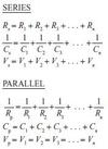
-Current through each R is equal. -Voltage drop on each at is a fraction of the terminal voltage. -Voltage drop on each R is PROPORTIONAL to resistance I(1) = I(2) V(1) = I(1)*R(1) V(2) = I(2) * R(2) R=R(1) + R(2) + R(3)
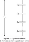
Capacitors wired in series
- “Seri-Q”; Veq is the sum of all individual V’s
- Q1=Q2
- Vs=V1+V2+V3+…+Vn
V is proportional to 1/C
- V1=Q1/C1
- V2=Q2/C2
- 1/Ceq = (1/C1) + (1/C2)+…+(1/Cn)

Capacitors wired in parallel
- “Par=C” ?
- resultant capacitance that is equal to the sum of the individual capacitances
- Cp=C1 + C2 + C3+…+Cn
- Vp=V1=V2=V3=…Vn

V of capacitor
Q/C
V of resistor (Vr)
Vr=IR
V terminal of RC circuit
V terminal = V of capacitor + V of resistor Vt=Vr + Vc
conventional current
convention assumes that all moving charges are positive, and thus, conventional current moves from regions of high electric potential to regions of low electric potential.
In the figure above, the conventional current moves through the circuit, from the positive terminal to the negative terminal.
direct current
where Δ q is the amount of charge that passes by in a certain amount of time, Δ t.
magnitude stays constant over time
electromotive force (EMF)
the electric potential difference (or voltage) that drives current. EMF isn’t really a force, it’s a potential difference.
Kirchhoff’s Loop Rule
The sum of the voltage drops across a closed circuit has to equal the sum of the voltage gains across the circuit.
resistance
of a conductor, R, is a measure of a particular conductor’s resistance to current flow
resistors.
Devices used to intentionally cause a voltage drop
resistivity, ρ
of a material is a measure of its resistance to current flow; if a material has a higher resistivity, then applying a given potential difference across it will produce a lower current. The resistance of a resistor depends of the resistivity of the material:
where A is the cross-sectional area through which the current flows, and L is the length of the resistor
ohmic
the voltage drop across them will be proportional to the current passing through them (conditions on MCAT unless otherwise stated)
Ohm’s Law
V=IR
Electric current
ampere
current units are coulombs per unit time
From Ohm’s Law, we see that the units of resistance must then be a volt per unit ampere, or an ohm
Resistors in Series configuration
When two or more resistors are in a series configuration, the current has no choice but to pass through all of them, one after the other.
In the diagram above, resistors R1 and R2 are in series. If you replaced the two series resistors by a single equivalent resistor, the total resistance would be: Req = R1 + R2
- What is the total resistance of the above circuit in ohms?
- How much current passes through each of the first and second resistors?
- How much current passes through the whole resistor?
- 4 ohms
- 2.5 A and 2.5 A
- 2.5 A
The equivalent resistance of the two series resistors is:
Req = 1 Ω + 3 Ω = 4 Ω
Now we can calculate the total amount of current flowing out of and into the battery, using Ohm’s Law:
Because the two resistors are in series, all 2.5 A of current passes through each of the resistors as it passes through the circuit.
The voltage drops across each resistor will be different. Across the 1-Ω resistor, the voltage drop is V1 = IR = (2.5 A)(1Ω ) = 2.5 V. Across the 3-Ω resistor, the voltage drop is V3 = IR = (2.5 A)(3Ω ) = 7.5 V. Notice that Kirchhoff’s loop rule still applies: the total voltage gain, due to the battery, is 10 V, and the total voltage drop across the two resistors is the same: 2.5 V + 7.5 V = 10 V.
Resistors in Parallel
When two or more resistors are in a parallel configuration, the current is split between the different paths, the voltage across each path is the same.
Req = (R1R2) / (R1+R2)
- What is the total resistance of the above circuit in ohms?
- How much current passes through the whole circuit?
- How much current passes through the 2Ω resistor?
- How much current passes through the 5Ω resistor?
- 10/7 Ohms
- 2.8 A
- 2 A
- 0.8 A
The equivalent resistance of the two parallel resistors can be calculated:
Now we can calculate the total amount of current flowing out of and into the battery, using Ohm’s Law:
Because the two resistors are in parallel, part of the 2.8 A of current passes through the 2-Ω resistor, and the other part passes through the 5-Ω resistor.
However, the voltage drops across each resistor are the same. Across the 2-Ω resistor, the current is:
Since the total current through the circuit is 2.8A, and 2A pass through the first circuit, we can use Kirchhoff’s junction rule to calculate the current through the second circuit. Knowing that the total current going through the circuit is equal to the sum of the currents going through each resitor, we can calculate the current through the second resitor to be 2.8A - 2.0A = 0.8A.
What is the equivalent resistance seen by the 25-V battery, in Ohms?
250 Ohms
The 160-Ω and the 200-Ω resistors at the top of the circuit are in series: . This is parallel with the 120-Ω resistor:
So the total equivalent resistance of the circuit is:
What current comes out of the battery?
0.1 A
Since the equivalent resistance of the circuit is 250 Ω , the total current in the circuit is:
What is the voltage drop across the last 160-Ω resistor?
16 V
The current (0.1 A) splits at point A, but comes back together at point B, before it passes through the last 160-Ω resistor. So, since we know the current and the resistance, we can calculate the voltage drop:
Since the total voltage drop across the circuit must be 25 V (the strength of the battery), the voltage drop between points A and B must then be 25 V – 16 V = 9 V.
Given that the voltage drop between points A and B is 9V, what is the current across the 120-Ω resistor?
0.075 A
There are two parallel branches between points A and B. Recalling that the voltage across each branch of a parallel setup is the same, we see that the voltage drop across the 120- resistor is 9V. We can apply Ohm’s Law one more time to calculate the current through that resistor:
internal resistance
(unlikely on MCAT but JIC)
Usually, the internal resistance of a battery is assumed to be zero. But when it takes on some non-zero value, it will reduce the effective terminal potential of the battery.
When a battery has internal resistance r, the terminal potential of the battery, V is less than the battery’s EMF, ε :
While it is still true that V = IR, the relationship between the current and the EMF of the battery is now different:
Capacitor
Two conductors with a potential difference between them, placed a short distance apart, can be used to store electrical energy.
capacitance
determines amount of charge that a capacitor can hold
When two uncharged conductors are connected to opposite terminals of a battery, equal amounts of positive and negative charge move to each of the conductors.
Farad
The units of capacitance are the Farad:
C=Q/V
V=U/q=Joules per coulomb
A 300 nF capacitor is connected to a 10 V battery. How much charge is stored on each plate of the capacitor?
3 microC
Applying the definition of capacitance, we can calculate the charge stored on each plate:
potential energy stored on a capacitor
When a battery is hooked up to an uncharged capacitor, it must do work in charging the capacitor. The electrical potential energy of the capacitor increases as work is done on it. When the capacitor is fully charged by a battery with terminal potential V,
parallel-plate capacitor
(How do you find its capacitance?)
two flat conducting plates, with surface area A, separated by distanced.
The capacitance of this configuration is:
where ε 0is the permittivity of free space, ε 0 =
Capacitors in series
When two or more capacitors are in series, each capacitor has to store the same amount of charge.
Since an equivalent capacitor would store a charge Q, when hooked up to a battery with terminal voltage V equal to:
each series capacitor will individually stores the same amount of charge:
Capacitances in series add like resistors in parallel:
Voltage drops with capacitors in parallel
Just like in the case of parallel resistors, the voltage drops across capacitors in parallel are the same.
Recall that in a parallel configuration of resistors, the current splits up between the branches. Similarly, the total charge stored is divided among capacitors in parallel. Since the total charge is spread over different capacitors with the same potential difference across their plates,
the equivalent capacitance of two parallel capacitors is the sum of the individual capacitances:
Again, notice that this equation is similar to the equivalent resistance of resistors in series.
If a 2-nF capacitor and a 3-nF capacitor are connected in parallel in a circuit with a 12-V battery, what is the total amount of charge stored by the circuit, when the capacitors are fully charged?
60 nC
As the two capacitors are in parallel, their equivalent capacitance is found by adding their individual capacitances:
Remember not to confuse the parallel resistor and parallel capacitor cases. If you’ve learned the resistor formulas, remember that the capacitor formulas are the opposite.
Since we know the voltage and the equivalent capacitance of the circuit, we can calculate the total charge stored:
dielectric
non-conducting material placed between the two plates of a capacitor. Air is a dielectric, as well as rubber, glass, and certain plastics. When a dielectric is inserted between the plates of a capacitor, the capacitance increases:
dielectric constant (k) of common materials
Alternating current(AC)
AC current and voltage will periodically reverse direction. In America, the direction of the current will change 60 times per second.
In a simple circuit, with resistors, the current will also vary sinusoidally in time:
root-mean-square (rms)
**Because the current and the voltage in an AC circuit change direction periodically, they average out to zero over time. **
If you measure the voltage or current at any particular time, the magnitude will be anything from zero to the maximum value.
To make calculation easier, the magnitude of AC voltage or current that is given is the root-mean-square (rms) value. Think of it as a kind of average.
The rms current and voltage are related to their maximum values:
Electric power
This means that when either the current or the voltage is high, more energy is transferred over a given amount of time.
On the other hand, this formula also applies to resistors. Applying Ohm’s Law, we see that the energy dissipated by a resistor as heat per unit time is:
P = I2R
The higher the resistance, the faster energy is dissipated.
In an AC circuit, use rms values of the current and voltage when calculating power.
If the current passing through resistor R1 is 3 A, what is the potential difference across resistor R2?
Parallel resistors: potential difference across each branch has the same potential drop:
9 V potential drop for each resistor.
What is the equivalent capacitance of this configuration?
To find the eqivalent capacitance of the capcitors in parallel (Cp), add:
Cp = 3nF + 5 nF = 8nF
The last capacitor is in series with Cp.
Calculate the equivalent capacitance of the entire configuration:
1/Ceq = (1/2nF) + (1/8nF) = (1/(5/8))nF
Ceq = 8/5 nF
What does the value of R have to be in order to make the equivalent resistance of the circuit equal to 4.5 ohms?
1. Solve for equivalent resistance of the 2 resistors in parallel (Rp):
1/Rp = 1/3 + 1/R = (R+3)/3R
Rp = 3R/(R+3)
2. Solve for equivalent resistance of the circuit:
Req = Rp +3
= [3R/(R+3)] +3
=[3R + 3(R+3)]/(R+3)
=(6R+9)/(R+3)
3. Since the equivalent resistance is 4.5 ohms, we can solve:
4.5 =(6R+9)/(R+3)
1.5R = 4.5
R=3 ohms
Kirchoff’s Junction Rule
At any point or junction in a circult, the sum of the currents directed into that point equals the sum of currents directed away form that point.
Kirchoff’s Loop Rule
Around any closed circuit loop, the sum of the voltage sources will always be equal to the sum of voltage (potential) drops.
- (per conservation of energy–all electrical energy gets fully used up by the other elements of the circuit)*
- Consequence of Conservation of Energy: law is in terms of voltage (J/C), not just energy (J)
Resistance
opposition within any material to the movement and flow of charge
- Low Resistance: conductors
- Middle resistance: Resistors
- *R=ρL/A**
- High resistance: insulators
Resistance of a Given Resistor
R=ρL/A
- ρ: resistivity (intrinsic quality)
- L: longer resistor electrons must travel greater distance through resistant material
- A: cross sectional area, more areas means more conduction paths (pathways) available to moving electons.
Most conductors have increased resistance and higher temperatures due to increased thermal oscillation of the atoms in the conductive material, producing a greater resistance to electron flow.
What is the relationship between V and emf (ε) if internal resistance of the wire is not negligible?
V < ε
(when current is not zero and rint is not negligible)
V=εcell - irint
Power of a resistor
P=iV=i2R=V2/R
RESISTORS IN PARALLEL
wired with a common high-potential terminal and a common low-potential terminal
For Parallel of Resistors: R1, R2, R3…Rn,
- total Voltage drop: Vp=V1=V2=V3=…=Vn
- Since V=iR: Resisance is additive too: 1/Rp=1/R1+1/R2+1/R3+…+1/Rn
Find the equivalent resistance for resistors in parallel:
Req=R1R2/R1+R2
PerKirchoff’s Rules:
- Total current is sum of all currents: itot=i1+i2+i3+…+in
- “Par-V” (V is the same ofr all Resistors)
- i1=Vp/R1
- i2=Vp/R2
- i3=Vp/R3

RESISTORS IN SERIES
wired with a common high-potential terminal and a common low-potential terminal
For series of Resistors: R1, R2, R3…Rn,
- total Voltage drop: Vs=V1+V2+V3+…+Vn
- Since V=iR: Resisance is additive too: Rs=R1+R2+R3+…+Rn

PARALLEL PLATE CAPACITORS
two electrically neutral metal plates are connected to a voltage source, positive charge builds up on the plate connected to the positive (higher voltage) terminal, and negative charge builds up on the plate connected to the negative (lower voltage) terminal
capacitance
- C=Q/V
- C=ε0(A/d)
- ε o is the permittivity of free space (8.85 × 10− 12 F/m), A is the area of overlap of the two plates, and d is the separation of the two plates.
Faraday constant
96,485 coulombs/mole e− )
Electric Field Between 2 plates
E=V/d
(uniform field, at a point in space between the plates of a parallel plate capcitor)
FYI: lightning occurs when a very, very large amount of charge exceeds the capacitance of the Earth’s surface and underside of the cloud (the two serving, approximately, as a parallel plate capacitor).
SUMMARY OF CIRCUIT ELEMENT MATHEMATICS

Alternating Current
Similar to direct current (DC):
- both are formed by moving electrons from low potential to high potential,
- motivated by emf,
- conform to Ohm’s law and Kirchhoff’s laws.
Difference is that
- AC is easier to produce and transport over long distances than DC.
- direct current flows in one direction only
- alternating current, as its name suggests, reverses direction periodically
- i=Imaxsin(2πft)=Imaxsin(ωt)
- where i is the instantaneous current at the time t, Imax is the maximum current, f is the frequency, and ω is the angular frequency ( ω = 2π f)

root-mean-square (rms) voltage
Vrms
Vrms=(Vmax)/√2)
root-mean-square (rms) current
Irms
Irms=(Imax)/√2)
Essential Equations: DC and AC Circuits
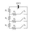
How would you draw the circuit below, with all switches closed in order to show parallel and series resistors?


