3: Sensing Flashcards
What is current?
ai)
The rate of flow of charged particles
What is Kirchhoff’s first law?
The total current entering a junction = the total current leaving it
What is potential difference?
aii)
energy (work done) per unit charge
potential difference equation for change in energy
V = ΔE / Q
Do you connect a voltmeter in parallel or series. Why?
Parallel because the p.d across components in parallel is the same
3.1what is joule heating, equation to calculate joule heating or wasted energy
potential difference that is lost by electrons in a wire getting obstructed by positive ions. this lost pd does work on the wire, heating it up, this wasted energy is known as dissipation
W = VIT
W = work done
also P = I2R
What is power? what’s it measured in and units
The rate of transfer of energy (the rate of work done)
measured in J s-1, which is the equivalent of the Watt (W)
equations for power
P = I V
P = I2 R (DISSIPATION)
How can you reduce the power dissipated during transmission of mains electricity?
P=IV Mains electricity is transmitted at a high voltage and low current to minimise the power dissipated
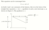
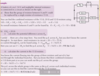
kirchoff’s first law means that current entering junction is the same as that leaving it, so in that parallel section there’s 0.1 A, so 0.4 - 0.1 = 0.3A going through I1,
as V1 is part of that parallel circuit, and pd is the same everywhere in a parallel circuit, V1 is 3.4V
so V2 is 6 - 3.4V = 2.6V
What is resistance?
equation
units?
A measure of how difficult it is to get a current to flow through a component
R = V / I
V A-1 (ohms Ω)
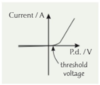
What is Ohm’s Law? describe the graph as well
If temperature is constant, the current through an ohmic conductor is directly proportional to the p.d across it (V=IR) The gradient of the IV graph is constant (so resistance is constant) and the graph goes through the origin
what is conductance
units, unit equivalence
how well electrons can flow through a conductor
conductance = 1 / R = I / V
the unit of conductance is A V-1 which is the Siemen (S)
how to work out resistance and conductance in series and parallel circuits
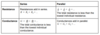
pd, current, conductance and resistances in parallel and series
How do you reduce the effect of random errors when investigating the I-V characteristic of a component?
Repeat your measurements and take averages
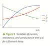
Describe and draw the I-V characteristic of a filament lamp, include pd against resistance and conductance
Why is it this shape?
current: A curve, which starts steep but then gets shallower as the p.d rises
Current flowing though the lamp increases its temperature, but current also dissipates energy through joule heating at a rate of (P = I²R) so its resistance increases. because of that, conductance decreases.
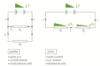
How can you investigate the I-V characteristic of a component using a test circuit?
1) Use a variable resistor to alter the p.d across the component and so the current flowing through it, record V and I
2) Plot a graph of current against p.d difference from your results. This graph is the I-V characteristic of the component
what is a conductor
Materials (such as metals) which have a high proportion of mobile charge carriers (free electrons), and can conduct electricity well.
semiconductors
Materials with a low proportion of mobile charge carriers, but the number of mobile charge carriers increases with a factor like light or temperature, enabling them to conduct electricity.
Under normal conditions, however, they do not conduct very well.
insulators
Materials with no (or very few) mobile charge carriers, which do not conduct electricity
What does the resistance of a wire depend on? Explain each one
1) Length. The longer the wire, the more difficult it is to make a current flow
2) Area. The wider the wire, the easier it will be for the electrons to pass along it
3) Resistivity. This depends on the material the wire’s made from, as the structure of the material may make it easy or difficult for charge to flow. Resistivity also depends on external factors like temperature
What affects how conductive a material is?
It’s number density of mobile charge carriers - the number of free electrons (or ions that are free to move) there are per cubic metre of the material.
The more mobile charge carriers a material has per unit volume, the better a conductor it will be
relationship between conductance and resistance with length of wire
resistance doubles if the length of the wire doubles so R ∝ L, and so conductance is G ∝ 1 / L
relationship between cross sectional area of a wire with resistance and conductance
conductance doubles if c.s.a doubles so G ∝ A, and resistance R ∝ 1 / A
relationship between conductivity and resistivity using their symbols
σ = 1 / p
σ = conductivity
p = resistivity
equation for conductivity using its constant
G = σA / L
3.3 equation for resistivity using its constant
R = pL / A
Why are metals good conductors?
They have loads of free electrons (charge carriers). The number density of mobile charge carriers is high
Explain how a metal’s conductivity is affected by temperature
As the electrons move, they scatter from the metallic lattice
As the temperature increases the lattice vibrates more, increasing the electron scattering, so the electrons are slightly less free to move
This means that as the temperature increases, the conductivity of a metal will slightly decrease
what is mean drift velocity
distance travelled of the electrons along the wire per second as they collide constantly
What is the equation linking current, the number of electrons, and the velocity of the electrons?
I = nAve
I = current (A)
n = n. density of electrons (m⁻¹)
A = cross sectional area (m²)
v = drift velocity (ms⁻¹)
e = charge of an electron (C)
What are Thermistors and LDRs, use for each
thermistor symbol
Examples of semiconductors.
In thermistors, increasing temp liberates electrons, enabling them to conduct and increasing conductivitiy, so reducing resistance
in LDRs it is light which liberates them. light falling on the LDRs increases conductivity, reducing resistance.
This means they can be used for temperature or light sensors.
What type of thermistor do we look at?
I-V graph for thermistor, temp and resistance graph
NTC negative temperature coefficient, as the temperature increases the resistance decreases
Describe an LDR and its circuit symbol
Light dependent resistor, sensitive to light The more light falls on it, the lower the resistance
Symbol: resistor in a circle with 2 arrows outside the circle, pointing towards centre of circle
Describe diodes
symbol for led and diodes
They are designed to let current flow in one direction only
What does forward bias (direction) mean when talking about diodes?
The direction in which the current is allowed to flow
Most diodes require a [] voltage of about 0.6 V in the [] direction before they will conduct
Threshold Forward
What happens in reverse bias (direction) with diodes?
The resistance of the diode is very high and the current that flows is very tiny
IV characteristic graph of a diode
symbol for diode and LED
Slightly negative current before threshold voltage where the current increases in a rough straight line
How is the p.d split in a potential divider circuit?
The p.d of the voltage source is divided in the ratio of the resistances
What can you use a potential divider circuit for?
Calibrating voltmeters,
you can choose the resistances to get the voltage you want
check whether the voltmeter reading is the same as the actual voltage across the component
ratio of resistances and voltages between 2 resistors
V1 / V2 = R1 / R2
potential divider equation for Vout and Vin
Vin = supply voltage
Vout = Vin * reistance of component at Vout/ total resistance
Why do batteries have resistance? What is it called? what does this do to the battery
In a battery, chemical energy is used to make electrons move. As they move, they collide with atoms inside the battery.
Internal resistance
internal resistance is what heats batteries up
What is e.m.f? what is it measured in
The amount of energy the battery (source) provides per unit charge (coulomb)
measured in volts
What is Kirchhoff’s second law?
The total emf around a series circuit = the sum of the p.ds across each component
What is load resistance?
The total resistance of all the components in the external circuit. Also called external Resistance
What is the terminal p.d?
The potential difference across the load resistance. It is the energy transferred when one coulomb of charge flows through the load resistance
What would happen if there was no internal resistance in the battery?
The terminal p.d would be the same as the e.m.f. However in real power supplies, there’s always some energy lost, as heat energy, overcoming the internal resistance
What are lost volts?
The energy wasted per coulomb overcoming the internal resistance
equation to find out Energy per coulomb supplied by the source
Energy per coulomb supplied by the source = energy per coulomb transferred in load resistance + energy per coulomb wasted in internal resistance
equations for emf and internal resistance
ε = V + v ε = I(R + r)
V = ε - v V = ε - Ir
ε = emf
V = terminal pd v = lost volts
I = current
R = load resistance r = internal resistance
an assumption that is made when calculating emf across a circuit
emf = Voltage at every component + internal resistance (lost voltage within the battery itself) we assume that there is no resistance from the connecting wires
How can you calculate emf and internal resistance from a I against V graph?
Start with V = ε - Ir Since ε and r are constants, this is an equation of a straight line. So the intercept with the vertical axis is ε And the gradient is -r
y = mx + c -> V = (-r)I + ε
how can a decrease in load resistance lead to a decrease in terminal pd
when load resistance R decreases, current increases because the total resistance R + r has decreased, but this also means the lost voltage, Ir, increases because I has so reducing the terminal PD
how to work out total emf in series circuits
and what is the condition
for cells in series you can calculate the total emf by adding the individual emfs
this requires all cells to be connected in the same direction
εtotal = ε1 + ε2 + ε3 …
How do you find the total emf of cells in series pointing in opposite directions?
Subtract emf of the ones facing in the opposite direction from the ones in the other direction
how to find total emf for identical cells in parallel
for identicall cells in parallel, the total emf is the same size as the emf of each individual identical cell.
this is because the current will split equally between identical cells.
εtotal = ε1 = ε2 = ε3 …
What is an easier way of measuring the emf of a power source?
Connect a voltmeter across its terminals. The current through the voltmeters is assumed to be negligible and so any difference between your measurements and the emf will be so small that the difference isn’t usually significant
How can you investigate internal resistance and emf?
1) Vary the current in the circuit by changing the value of the load resistance using the variable resistor 2) Measure the p.d for several different values of current 3) Record the data for V and I, and plot the results in a graph of V against I, then calculate emf and internal resistance
What assumption do you make in any experiment using voltmeters and ammeters?
You can assume that the voltmeter has a very high resistance, and the ammeter has a very low resistance
Why is it hard to choose the value for the load resistance, when investigating emf and internal resistance?
A low load resistance will give a large current, which will reduce the percentage uncertainty in the ammeter reading of the current. But large currents will cause significant heating in the wires, which will invalidate your results
Why does including an ammeter in the circuit not affect the current trough the variable resistor? (Investigating emf and internal resistance)
The ammeter has a resistance that’s so low it’s negligible, and so the voltage across it is also negligible
Why does including a voltmeter in the circuit not affect the current through the variable resistor? (Investigation of emf and internal resistance)
Voltmeters have a very high internal resistance, so the current through them is so low you can usually assume it is negligible
When investigating internal resistance and emf, how can you reduce the effect of heating the wires?
Include a switch in your circuit to turn off the current whenever possible to reduce the effect of heating in the wires on the resistance of the circuit
answer on q
thermistor practical
how to improve
place thermistor in beaker of boiling water containing crushed ice and measure temperature with a thermometer at selected regular intervals (5 degrees), make sure to stir before taking a reading to get an accurate measurement
can improve using water bath with thermostat
cool slowly to reduce temp fluctuations
