SOP Chapter 3 Flashcards
3-1.1 Kinds of Airplane Operation
- Day and night operations
- VFR and IFR
- Flight in icing conditions
- The airplane is certified for ditching when the safety equipment specified by the applicable regulations is installed.
- The airplane is certified capable of RVSM operations
3-1.1 Kinds of Airplane Operation
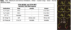
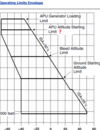
RVSM REQUIRED EQUIPMENT LIST
EQUIPMENT: REQUIREMENTS FOR RVSM
AUTOPILOT (1): MUST BE OPERATIONAL
ALTITUDE ALERTING SYSTEM: MUST BE OPERATIONAL ALTITUDE REPORTING TRANSPONDER (2): ONE (1) MUST BE OPERATIONAL
AIR DATA COMPUTERS (2) TWO : (2) MUST BE OPERATIONAL

Memory Item - Double Boxed
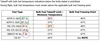
3-2 STRUCTURAL WEIGHT LIMITATIONS
CRJ700 Structural Weight Limitations
CRJ900 Structural Weight Limitations
CRJ550 Structural Weight Limitations
CRJ 900, 700, 550
Maximum Taxi and Ramp Weight 85,000 lbs==75250==66000
Maximum Takeoff Weight 84,500 lbs==75000===65000
Maximum Landing Weight 75,100 lbs==67000==61==
Maximum Zero Fuel Weight 70,750 lbs==62300==59000
Minimum Flight Weight 45,000 lbs==42000==42000
====================================
Minimum Operating Empty Weight 39,835 lbs (only crj700)
===================================
Note: The maximum takeoff weight (MTOW) and/or maximum landing weight (MLW) may be further limited due to performance consideration(s).

The information presented in this chapter (chapter 3 of sop - limitations) contains limitations that have been extracted from the
Aircraft Flight Manual (AFM) and
Flight Crew Operating Manual (FCOM).
The limitations in this chapter are not all inclusive.

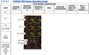
3-3.1 CRJ700 Center-of-Gravity Limits

3-3.2 CRJ550 Center-of-Gravity Limits

3-3.3 CRJ900 Center-of-Gravity Limits

3-4 ALTITUDE AND TEMPERATURE OPERATING LIMITS
- Maximum airport pressure altitude for takeoff and landing
Maximum airport pressure altitude for takeoff and landing is 8,000’

3-4 ALTITUDE AND TEMPERATURE OPERATING LIMITS
- Maximum operating altitude
Maximum operating altitude is 41,000’

3-4 ALTITUDE AND TEMPERATURE OPERATING LIMITS
- The maximum ambient air temperature approved for takeoff and landing
The maximum ambient air temperature approved for takeoff and landing is ISA +35°C.

3-4 ALTITUDE AND TEMPERATURE OPERATING LIMITS
- The minimum ambient temperature approved for takeoff
The minimum ambient temperature approved for takeoff is -40°C (-40°F).

Memory Item - Double Boxed
3-5 OPERATION IN ICING CONDITIONS
3-5.1 Cowl Anti-Ice System
3-5.1.1 Ground Operations
Cowl anti-ice system must be ON when the OAT is 10°C (50°F) or below:
- and visible moisture in any form is present (such as fog with visibility of 1,500 meters [1 mile] or less, rain, snow, sleet and ice crystals)
- when operating on runways, ramps or taxiways where surface snow, ice, standing water, or slush is present

Memory Item - Double Boxed
3-5 OPERATION IN ICING CONDITIONS
3-5.1 Cowl Anti-Ice System
3-5.1.3 Flight Operations
Icing conditions exist in-flight at a TAT of 10°C (50°F) or below, and visible moisture in any form is encountered (such as clouds, rain, snow, sleet or ice crystals), except when the SAT is -40°C (-40°F) or below.
The engine cowl anti-ice system must be ON when:
- in icing conditions, or
- ICE is annunciated by the ice detection system

Memory Item - Double Boxed
3-5 OPERATION IN ICING CONDITIONS
3-5.3 Wing Anti-Ice System
3-5.3.1 Ground Operations
Wing anti-ice system must be ON for takeoff when the OAT is 5°C (41°F) or below and:
- visible moisture in any form is present (such as fog with visibility of 1,500 meters [1 mile] or less, rain ,snow, sleet and ice crystals)
- the runway is contaminated with surface snow, slush or standing water
When Type II or Type IV anti-icing fluids have been applied:
• wing anti-ice system must only be selected ON, if required, just prior to thrust increase for takeoff

Memory Item - Double Boxed
3-5 OPERATION IN ICING CONDITIONS
3-5.3 Wing Anti-Ice System
3-5.3.3 Flight Operations
Icing conditions exist in-flight at a TAT of 10°C (50°F) or below, and visible moisture in any form is encountered (such as clouds, rain, snow, sleet or ice crystals), except when the SAT is -40°C (-40°F) or below.
The wing anti-ice system must be ON when:
- ICE is annunciated by the ice detection system, or
- in icing conditions and the airspeed is less than 230 KIAS
NOTE Do not hold in icing conditions with Slats/Flaps extended.

Memory Item - Double Boxed
3-5 OPERATION IN ICING CONDITIONS
3-5.5 Supercooled Large Droplet Icing
Continued operation in areas where supercooled large droplet (SLD) icing conditions exist is prohibited.
SLD icing conditions are indicated by ice accretion on the flight deck side windows.
- wing and cowl anti-icing systems must be ON in SLD icing conditions
- leave icing conditions when side window icing occurs

Memory Item - Double Boxed
3-6 COLD WEATHER OPERATIONS
Take-off is prohibited with frost, ice, snow or slush adhering to any critical areas (wings, upper fuselage, horizontal stabilizer, vertical stabilizer, control surfaces, and engine inlets).

3-6 COLD WEATHER OPERATIONS
Takeoff is permitted with frost adhering to:
• The upper surface of the fuselage if it is possible to distinguish surface features. See WOP 2.13.1;
and/or
• Maximum 1/8 in (3.0 mm) layer of frost on the underside of the wing that is caused by cold soaked fuel.
Comprehensive procedures for operating in cold weather are provided in the WOP.

3-7 RUNWAY SLOPES
The maximum runway slopes approved for takeoff and landing are:
- +2% (uphill)
- -2% (downhill)
Memory Item - Double Boxed
3-8 TAILWIND CONDITIONS
The maximum tailwind component approved for takeoff and landing is ====== knots.
10 knots.
3-9 MINIMUM FLIGHT CREW
The minimum flight crew is
one (1) pilot and one (1) copilot.
3-10 FLIGHT DECK DOOR
- The flight deck door must be kept closed and locked at all times during flight except to permit access and egress in accordance with the approved procedures for opening, closing and locking the door.
- Any time the flight deck door is opened in-flight, a challenge and response closing and locking verification must be used to verify that the door is closed and locked.
- Any time one of the required flight crew leaves the flight deck another crew member must be present in the flight deck to ensure that the required crew member is not locked out of the flight deck.
3-11 CARGO
Flight must be within ==== minutes of a suitable airport, if cargo is carried in any ===========
Flight must be within 60 minutes of a suitable airport, if cargo is carried in any labeled cargo compartment.
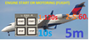
Aircraft Stowage/Cargo Dimensions
3-11 CARGO

3-12 OZONE CONCENTRATION
limits?
Airplane operations are prohibited on routes where ozone concentrations will exceed the following limits:
- 0.25 parts per million by volume, sea level equivalent, at any time above flight level 320, and
- 0.1 parts per million by volume, sea leve
3-12 OZONE CONCENTRATION
‘Sea level equivalent’ refers to ???
‘Sea level equivalent’ refers to conditions of 25°C and 760 millimeters of mercury pressure.
Airplane operations are prohibited on routes where ozone concentrations will exceed the following limits:
- 0.25 parts per million by volume, sea level equivalent, at any time above flight level 320, and
- 0.1 parts per million by volume, sea level equivalent, time-weighted average during any three (3) hour interval above flight level 270
3-12 OZONE CONCENTRATION
Data to determine flight altitudes and/or duration at altitude in compliance with these requirements are given in
Flight Planning and Cruise Control Manual, Chapter 6, SPECIAL OPERATIONS, Maximum Allowable Cabin Ozone Concentration. Flight crews may utilize SOP 3-28.3, Maximum Flight Duration at Altitude Due to Cabin Ozone Concentration, for determining flight duration at altitudes higher than originally planned by Dispatch.
3-13 ENGINES
3-13.1 Engine Indications
The CRJ700 and CRJ550 aircraft use two (2) General Electric ============= engines.
The CRJ900 aircraft uses two (2) General Electric ============= engines.
The CRJ700 and CRJ550 aircraft use two (2) General Electric CF34-8C5B1 engines.
The CRJ900 aircraft uses two (2) General Electric
CF34-8C5 engines.
3-13 ENGINES
3-13.1 Engine Indications
The engine limit display markings on ======= must be used to determine compliance with the maximum/minimum limits and precautionary ranges.
If EICAS markings show more conservative limits than those specified in sop chapter 3, the limit markings on the ======== must be used.
The engine limit display markings on EICAS must be used to determine compliance with the maximum/minimum limits and precautionary ranges.
If EICAS markings show more conservative limits than those specified sop chapter 3, the limit markings on the EICAS must be used.
3-13 ENGINES
3-13.1 Engine Indications


3-13.2 Powerplant Intermix
Powerplant intermix operations are prohibited
3-13.3 Engine Warm-up
The engine must remain at ———– until oil pressure reaches
The engine must remain at IDLE until oil pressure reaches normal operating range.

3-13.3 Engine Warm-up
During all starts, do not exceed —- for ——- minutes after start, or ——————–]
???
During all starts, do not exceed 75% N1 for
two (2) minutes after start,
or until all operating indications are in the normal range, whichever is longer.

3-13.4 Thrust Management Data
With the engines running and bleeds configured for take-off, the crew must verify ………………….. .
Refer to ……………. .
With the thrust levers set for take-off, ——-and ——— values should ————–.
3-13.4 Thrust Management Data
With the engines running and bleeds configured for take-off, the crew must verify that the target N1 values correspond to the data presented in the thrust setting charts (± 1.0%).
Refer to PERFORMANCE – THRUST SETTINGS. With the thrust levers set for take-off, target and actual N1 values should match.
**** Memory Item - Double Boxed *****
3-13.5 Engines High-Power Schedule Switchlight
Use of the ENGINES HIGH PWR SCHEDULE switchlight is
prohibited.

3-13.7 Engine Operating Limits

N1?

3-13.7 Engine Operating Limits

N2?

**** Memory Item - Double Boxed *****
3-13.7 Engine Operating Limits
ITT?


3-13.7 Engine Operating Limits

OIL TEMP?

**** Memory Item - Double Boxed *****
3-13.7 Engine Operating Limits
OIL Pressure?


3-13.7 Engine Operating Limits

MINIMUM OIL LEVEL FOR FLIGHT?

**** Memory Item - Double Boxed *****
3-13.7 Engine Operating Limits
[1] Normal takeoff power and maximum power (two engines) is limited to ——– minutes.

[1] Normal takeoff power and maximum power (two engines) is limited to 5 minutes.
**** Memory Item - Double Boxed *****
3-13.7 Engine Operating Limits
[2] APR power (one engine) is limited to 10 minutes.

[2] APR power (one engine) is limited to 10 minutes.
**** Memory Item - Double Boxed *****
3-13.7 Engine Operating Limits
[3] ITT must be below ———- before attempting to ground start engine.

[3] ITT must be below 120°C before attempting to ground start engine.
3-13.7 Engine Operating Limits
[4] ITT must be below ———- before attempting to air start engine.

[4] ITT must be below 90°C before attempting to air start engine.
3-13.7 Engine Operating Limits
[5] Maximum oil pressure is limited to ——— psi when oil temperature transient is less than ———— .

[5] Maximum oil pressure is limited to 156 psi when oil temperature transient is less than 60°C.
3-13.7 Engine Operating Limits
[6] Oil pressures (above IDLE) between ………………..
????

[6] Oil pressures (above IDLE) between 25 and 45 psi require oil temperature monitoring.
3-13.7 Engine Operating Limits
- [7] Oil pressures should show ——— value during start and may peak beyond———- max display value).
- Oil pressures ———- are displayed as amber dashes.
- Oil pressure may be greater than …………….. minutes

- [7] Oil pressures should show positive value during start and may peak beyond 182 psi (max display value).
- Oil pressures above 182 psi are displayed as amber dashes.
- Oil pressure may be greater than 95 psi for a maximum of ten (10) minutes

3-13.9 Airplane Cold Soak
Before the first flight of a day, when the airplane is cold-soaked at an ambient temperature of -30°C (-22°F)
or below for more than eight (8) hours:
- the engines must be motored for 60 seconds and the fan rotation must be verified before an engine start is initiated
- thrust reversers must be actuated until the deploy and stow cycles are two (2) seconds or less

**** Memory Item - Double Boxed *****
3-13.11 Continuous Engine Ignition
Continuous engine ignition must be used during the following:
- takeoffs and landings on contaminated runways
- flight through moderate or heavier intensity rain
- flight through moderate or heavier intensity turbulence
- flight in the vicinity of thunderstorms

**** Memory Item - Double Boxed *****
3-13.12 Reduced (FLEX) Takeoff Thrust
Note: FLEX thrust may be used for takeoff on wet runways, ….
????
Note: FLEX thrust may be used for takeoff on wet runways, provided the flight crew selects “WET” runway performance data on the FMS MCDU (ACARS) PERF WT & BALANCE, CONDITIONS, page 1
**** Memory Item - Double Boxed *****
3-13.12 Reduced (FLEX) Takeoff Thrust
The use of Reduced/FLEX thrust for takeoff is not authorized when:
- Wing and/or cowl anti-ice bleeds are in use
- Runway is contaminated with standing water, slush, snow, or ice*
- Warnings or forecasts of windshear or downdrafts exist (including LLWAS advisories)
- Antiskid system is inoperative
- The engine cannot achieve full rated thrust **

3-13.13 Engine Starter
3-13.13.1 Associated Starter Conditions
The starter must not be used if
The starter must not be used if indicated N2 rpm exceeds 45%.
3-13.13 Engine Starter
3-13.13.1 Associated Starter Conditions
At initiation of thrust lever movement from SHUT OFF to IDLE:
- ITT must be 120°C or less for all ground starts
- ITT must be 90°C or less for all air starts
**** Memory Item - Double Boxed *****
3-13.13.3 CRJ Starter Cranking Limits
All


3-13.13.3 CRJ Starter Cranking Limits
Ground Start


**** Memory Item - Double Boxed *****
3-13.13.3 CRJ Starter Cranking Limits
Ground , Motoring


**** Memory Item - Double Boxed *****
3-13.13.3 CRJ Starter Cranking Limits
Flight
Motoring & Starter


**** Memory Item - Double Boxed *****
3-13.13.3 CRJ Starter Cranking Limits
All


3-13.13.5 Engine Relight Limitations
3-13.13.5.1 CRJ550/700 (CF34-8C5B1) Engine Relight Limitations
3-13.13.5.3 CRJ900 (CF34-8C5) Engine Relight Limitations
Windmilling
Starter Assisted
All-Engine-Out Rapid Relight
Note: FADEC rapid relight capability has been demonstrated at 200 KIAS for up to 15-second fuel interruptions.

3-13.13.5 Engine Relight Limitations
3-13.13.5.1 CRJ550/700 (CF34-8C5B1) Engine Relight Limitations
Windmilling
Starter Assisted
All-Engine-Out Rapid Relight

3-13.13.5 Engine Relight Limitations
3-13.13.5.3 CRJ900 (CF34-8C5) Engine Relight Limitations
Windmilling
Starter Assisted
All-Engine-Out Rapid Relight

900 Engine Start Envelope Figure
Note: Special All-Engine-Out rapid relight envelope is from ——————– to ————— and ——————- to ———————- KIAS.
Note: Special All-Engine-Out rapid relight envelope is from 10,000’ to SL and 200 to 250 KIAS.

550/700 Engine Start Envelope Figure
Note: Special All-Engine-Out rapid relight envelope is from ——————– to ————— and ——————- to ———————- KIAS.
Note: Special All-Engine-Out rapid relight envelope is from 10,000’ to SL and 200 to 250 KIAS.

3-14 ENGINE OPERATING LIMITS DUE TO WIND DIRECTION
Within 30° on either direction of the airplane nose; no windspeed limit. -OR- >30° in either direction of the airplane nose; < 5 knots windspeed.

3-14 ENGINE OPERATING LIMITS DUE TO WIND DIRECTION
>30° in either direction of the airplane nose; between 5 and 30 knots windspeed.

3-14 ENGINE OPERATING LIMITS DUE TO WIND DIRECTION
>30° in either direction of the airplane nose; >30 knots windspeed.

3-15.1 Fuel Quantities
——————— fuel quantity must be monitored throughout the flight.
Center tank fuel quantity must be monitored throughout the flight.
**** Memory Item - Double Boxed *****
3-15 FUEL
The maximum permissible fuel imbalance between the contents of the left wing tank and the right wing tank are given below:
during takeoff:
• during takeoff: 300 lbs (136 kg)
**** Memory Item - Double Boxed *****
3-15 FUEL
The maximum permissible fuel imbalance between the contents of the left wing tank and the right wing tank are given below:
• all other phases of flight:
• all other phases of flight: 800 lbs (363 kg)
3-15 FUEL
Fuel remaining in a tank when the appropriate fuel quantity indicator reads zero is —————-
is not usable.
3-15 FUEL
Fuel quantities are based on —————– lbs per U.S. gal and ———– lbs per kg conversion factors.
Fuel quantities are based on 6.75 lbs per U.S. gal and 2.2046 lbs per kg conversion factors.
3-15.1 Fuel Quantities
The maximum usable fuel load for
All Tanks
Pressure Refueling
550 , 700 and 900 all are the same

3-15.1 Fuel Quantities
The maximum usable fuel load for
Center Tank
Pressure Refueling
550 , 700 and 900 all are the same

3-15.1 Fuel Quantities
The maximum usable fuel load for
All Tanks
Pressure & Greavity
Refueling

**** Memory Item - Double Boxed *****
What is Takeoff with a fuel in the center tank limitation?
Takeoff with a fuel load in excess of 500 lbs in the center tank is not permitted unless:
- each main wing tank is above 4,400 lbs, or
- if each main wing tank is less than 4,400 lbs consult the Aircraft Flight Manual’s Limitations section for additional requirements
The minimum fuel quantity for go-around
is 600 lbs per wing tank (with the airplane level)
and
assuming a maximum airplane climb altitude of 10° nose up.
Fuel quantity diference limitation for ground opeeration:
For ground operations, the right and left tank quantities should never have a difference greater than 2500 lbs.
3-15.3 Fuel Temperature
Takeoff with engine fuel temperature indications below
5°C (41°F) is prohibited.
3-15.3 Fuel Temperature
Takeoff with bulk fuel temperature indications below the limits stated is prohibited.
.
During flight, bulk fuel temperature must remain above the applicable bulk fuel freezing point

3-15.4 Fuel Grades
For approved grades and mixing of fuels consult the
Airplane Flight Manual.
3-15.5 Fuel Additives
For approved additives and their concentrations,
For approved biocide additives and their concentration
For approved anti-static additive and its concentration
For approved fuel conductivity additive and its concentration
For approved corrosion inhibitors and their concentration
consult the Aircraft Flight Manual’s Limitations section.
3-15.6 Fuel Crossflow
CrossFlow Limitation for takeoff ?
Powered crossflow and gravity crossflow must be OFF for takeoff.
3-16 OIL
3-16.1 Oil Consumption
Maximum oil consumption on each engine is ????
Maximum oil consumption on each engine is 189 cubic centiliters per hour
(6.4 U.S. ounces per hour)
(0.05 U.S. gallons per hour).
3-16.2 Oil Grades
Mixing of different types of oils is ?????
Mixing of different types of oils is prohibited.
3-16.2 Oil Grades

3-16.3 Engine Oil Level Engine oil levels must be checked as follows:
- the maximum duration without engine oil servicing is 36 operating hours
- for airplane operations in excess of 36 operating hours (without engine oil tank servicing), the engine oil level must be checked within three (3) minutes to two (2) hours after every engine shutdown
• the maximum duration without engine oil servicing is
36 operating hours
for airplane operations in excess of 36 operating hours (without engine oil tank servicing), the engine oil level must be checked
within three (3) minutes to two (2) hours after every engine shutdown
3-16.5 Oil Replenishment System
If use of the oil replenishment system is required, then the engine(s) should be replenished within 15 minutes to two (2) hours after engine shutdown.
3-17 AUXILIARY POWER UNIT
Model?
Allied Signal RE 220 (RJ)
3-17 AUXILIARY POWER UNIT
3-17.1 Starting
Minimum ambient temperature for starting a cold-soaked APU on the ground is
-40°C (-40°F)
3-17 AUXILIARY POWER UNIT
3-17.1 Starting
Maximum EGT (dependant upon altitude and temperature)
• 0 to 100 % RPM 692ºC to 1038ºC

3-17 AUXILIARY POWER UNIT
3-17.1 Starting
The APU starter motor duty cycle is limited to not more than
3 starts/start attempts in 1 hour.
**** Memory Item - Double Boxed *****
3-17 AUXILIARY POWER UNIT
3-17.1 Starting
NOTE A
????? minute delay must be observed between cranking attempts to allow for ???????
2 minute delay must be observed between cranking attempts to allow for cooling of starter and starter contactor and APU fuel drainage.
3-17.3 APU Operating Range
Maximum RPM: ????
Maximum EGT: ????
Maximum RPM: 106%
Maximum EGT: 1038°C (do not exceed under any operating condition).
3-17.5 APU Bleed Air
Bleed air extraction limit????
APU bleed air extraction is not permitted above 25,000 feet.
3-17.5 APU Bleed Air
Engine start during ground operations
is there any limit???
No bleed air extraction limitation.
Each engine may be started using the APU as a bleed air source.
3-17.7 APU Generator
The maximum permissible load on the APU generator is ?????
The maximum permissible load on the APU generator is 40 kVA.
3-17.9 APU Indications
To determine compliance with the maximum limit and precautionary APU ranges????
The APU limit display markings on the EICAS must be used to determine compliance with the maximum limit and precautionary ranges.
If EICAS markings show more conservative limits than those specified below, the limit markings on the EICAS should be used.
NOTE
Red — Maximum Limitations
Green — Normal Operating Range

3-17.9 APU Indications
APU EGT
Red: ???
Green: ???
APU EGT
Red: 807 °C
Green: 0 to 806 °C
The APU limit display markings on the EICAS must be used to determine compliance with the maximum limit and precautionary ranges. If EICAS markings show more conservative limits than those specified below, the limit markings on the EICAS should be used.

3-17.9 APU Indications
APU RPM %
Red: ???
Green: ???
APU RPM %
Red: 107
Green: 0 to 106
The APU limit display markings on the EICAS must be used to determine compliance with the maximum limit and precautionary ranges. If EICAS markings show more conservative limits than those specified below, the limit markings on the EICAS should be used.

3-17.13 APUEnvelope
Load Limit


3-17.13 APU Envelope
Altitude Starting Limit


3-17.13 APU Envelope
Bleeed Altitude Limit


3-17.13 APU Envelope
Ground Start Alt Limit


**** Memory Item - Double Boxed *****
3-18 MAXIMUM OPERATING SPEED AND MACH NUMBER
The CRJ550/700 Maximum cruise Mach number during flight in RVSM airspace is ????
The CRJ900 Maximum cruise Mach number during flight in RVSM airspace is ?????
The CRJ550/700 Maximum cruise Mach number during flight in RVSM airspace is 0.83.
The CRJ900 Maximum cruise Mach number during flight in RVSM airspace is 0.82.
**** Memory Item - Double Boxed *****
3-20 FLAPS EXTENDED SPEEDS
CRJ550/700 VFE CRJ900 VFE
Flaps 1??? KIAS ????? KIAS

CRJ550/700 VFE CRJ900 VFE

**** Memory Item - Double Boxed *****
3-20 FLAPS EXTENDED SPEEDS
CRJ550/700 VFE CRJ900 VFE
Flaps 8??? KIAS ????? KIAS

CRJ550/700 VFE CRJ900 VFE

**** Memory Item - Double Boxed *****
3-20 FLAPS EXTENDED SPEEDS
CRJ550/700 VFE CRJ900 VFE
Flaps 20??? KIAS ????? KIAS

CRJ550/700 VFE CRJ900 VFE

**** Memory Item - Double Boxed *****
3-20 FLAPS EXTENDED SPEEDS
CRJ550/700 VFE CRJ900 VFE
Flaps 30??? KIAS ????? KIAS

CRJ550/700 VFE CRJ900 VFE

**** Memory Item - Double Boxed *****
3-20 FLAPS EXTENDED SPEEDS
CRJ550/700 VFE CRJ900 VFE
Flaps 45??? KIAS ????? KIAS

CRJ550/700 VFE CRJ900 VFE

**** Memory Item - Double Boxed *****
3-21 MAXIMUM LANDING GEAR OPERATING SPEEDS
Extension ?
Down and Locked ?
Retraction?
Extension 220 KIAS
Down and Locked 220 KIAS
Retraction 200 KIAS
3-22 TIRE LIMIT SPEED
CRJ550/700 maximum tire limit speed is ????
CRJ900 maximum tire limit speed is ????
CRJ550/700 maximum tire limit speed is 182 knots ground speed. CRJ900 maximum tire limit speed is 195 knots ground speed.
3-23 MAXIMUM AIRSPEED FOR ADG OPERATION
??
The maximum speed for ADG operation is VMO/MMO.
**** Memory Item - Double Boxed *****
3-24 TURBULENCE PENETRATION SPEED
Maximum airspeed for turbulence penetration is 280 KIAS or 0.75 Mach, whichever is lower.
3-25 MINIMUM OPERATING SPEED LIMIT
??
Intentional speed reduction below the onset of stall warning, as defined by stick shaker operation, is prohibited unless a lower speed is specifically authorized for flight test or training operations.
3-26 WINDSHIELD WIPER OPERATION
The windshield wiper must not be operated above 250 KIAS.
3-26 WINDSHIELD WIPER OPERATION
If the windshield wiper has failed in a non-parked position, ????
If the windshield wiper has failed in a non-parked position, the airplane speed must not exceed 250 KIAS
3-27 MANEUVERING LIMIT LOAD FACTORS
Phase of Operation Maximum “G” Loading
Flaps Retracted ???
Phase of Operation Maximum “G” Loading
Flaps Retracted -1.0 to 2.5 G
Flaps Extended 0.0 to 2.0 G
3-27 MANEUVERING LIMIT LOAD FACTORS
Phase of Operation Maximum “G” Loading
Flaps Extended ???
Phase of Operation Maximum “G” Loading
Flaps Extended 0.0 to 2.0 G
3-28 AIR-CONDITIONING AND PRESSURIZATION
The maximum relief differential pressure is ——– psi.
The maximum relief differential pressure is 8.7 psi.
3-28 AIR-CONDITIONING AND PRESSURIZATION
The maximum negative differential pressure is ——— psi.
The maximum negative differential pressure is -0.5 psi.
3-28 AIR-CONDITIONING AND PRESSURIZATION
During taxi, takeoff and landing, the pressure differential must not exceed ———– psi.
During taxi, takeoff and landing, the pressure differential must not exceed 0.1 psi.
3-28 AIR-CONDITIONING AND PRESSURIZATION
Prior to opening any of the airplane doors ………..
The airplane must be completely depressurized prior to opening any of the airplane doors.
3-28 AIR-CONDITIONING AND PRESSURIZATION
To preclude possible crew and/or passenger ear damage,————–
To preclude possible crew and/or passenger ear damage, use of the EMERG DEPRESS switch above 15,000’ is prohibited.
3-28.1 Single Pack Operation
The CRJ550/700 maximum altitude for single pack operation is
?????????????
The CRJ550/700 maximum altitude for single pack operation is 31,000’.
3-28.1 Single Pack Operation
The CRJ900 maximum altitude for single pack operation is
?????????????
The CRJ900 maximum altitude for single pack operation is 25,000’.
**** Memory Item - Double Boxed *****
3-29 AUTOMATIC FLIGHT CONTROL SYSTEM
3-29.3 CRJ900 Automatic Flight Control System

**** Memory Item - Double Boxed *****
3-29 AUTOMATIC FLIGHT CONTROL SYSTEM
3-29.1 CRJ550/700 Automatic Flight Control System

3-30 ELECTRICAL SYSTEMS
3-30.1 Permissible AC Electrical System Loads
Individual AC generator loading must not exceed the following values:
0 to 41,000’
Load Limitation
Main Generator (each) 40 kVA
APU Generator 40 kVA
3-30.3 Permissible DC Electrical System Loads
In-flight:
• maximum permissible continuous load on each TRU is ????
• maximum permissible continuous load on each TRU is 120 amps
**** Memory Item - Double Boxed *****
3-30.3 Permissible DC Electrical System Loads
Ground Operation:
• to protect the CRT displays, the maximum permissible time for ground operations with DC power is ??????
Ground Operation:
• to protect the CRT displays, the maximum permissible time for ground operations with DC power is 5 minutes.
3-30.5 Circuit Breaker Reset
(In Flight)
A circuit breaker must not be reset or cycled (i.e., opened or closed) unless doing so is consistent with explicit procedures specified in the Airplane Flight Manual or unless, in the judgment of the Pilot in Command, that resetting or cycling of the circuit breaker is necessary for the safe completion of the flight.
**** Memory Item - Double Boxed *****
3-31 FLIGHT CONTROLS – LIFT/DRAG DEVICES
3-31.1 Slats/Flaps
Is there any limitation?
Enroute use of Slats/Flaps is prohibited.
Flight with Slats/Flaps extended at altitudes above 15,000’ is prohibited.
**** Memory Item - Double Boxed *****
3-31.3 Flight Spoilers
Is there any limitation?
1- Flight spoilers must not be extended in-flight below an altitude of 300’ AGL
2- To ensure adequate maneuver margins, flight spoilers must not be extended in-flight at airspeeds below the recommended approach speed plus 10 KIAS.
3-31.5 Stall Protection
Any limitation?
Both stall protection system switches must remain on for all phases of flight.
3-32 THRUST REVERSERS
Activation in flight in-flight????
Thrust reversers are approved for ground use only, activation of the reverse thrust levers is prohibited in-flight.
3-32 THRUST REVERSERS
Go- Around?
The thrust reversers are intended for use during full stop landings.
Do not attempt a go-around maneuver after deployment of the thrust reversers.
3-32 THRUST REVERSERS
Takeoff with icons or EICAS warning and/or caution messages
???
Takeoff with any thrust reverser icons or EICAS warning and/or caution messages displayed is prohibited
3-32 THRUST REVERSERS
During landing, maximum reverse thrust is prohibited below ——– KIAS, and reverse idle should be achieved by ———- KIAS.
During landing, maximum reverse thrust is prohibited below 75 KIAS, and reverse idle should be achieved by 60 KIAS.
Backing-up using thrust reversers
???
Backing-up using thrust reversers is prohibited.
**** Memory Item - Double Boxed *****
3-33 TAXI LIGHTS
ANY LIMITATION?
The taxi lights must be switched OFF whenever the airplane is stationary in excess of 10 minutes.
3-34 WHEEL BRAKE COOLING LIMITATIONS
Brake cooling times must be observed between a landing or rejected takeoff (RTO) and a subsequent takeoff to:
ensure that sufficient brake energy is available to bring the airplane to a complete stop, if the subsequent takeoff is rejected.
3-34.1 CRJ900 Anti-Skid
ANY LIMITATION?
With an anti-skid channel inoperative on the CRJ900, takeoff from a wet runway is prohibited.
3-35 MISCELLANEOUS LIMITATIONS
3-35.3 Minimum Descent Altitude
When setting the MDA/DDA marker on the barometric altimeter using the DH/MDA/DDA knob on the altitude reference panel, the next highest 10-foot increment must be selected if the altitude is not at a 10-foot increment.
3-35 MISCELLANEOUS LIMITATIONS
3-35.3 Minimum Descent Altitude
When setting the MDA/DDA marker on the barometric altimeter using the DH/MDA/DDA knob on the altitude reference panel, the next highest 10-foot increment must be selected if the altitude is not at a 10-foot increment.
3-35 MISCELLANEOUS LIMITATIONS
3-35.5 Traffic Alert and Collision Avoidance System (TCAS)
Pilots are authorized to deviate from their Air Traffic Control (ATC) clearance in order to comply with a TCAS resolution advisory (RA) command.
Pilots shall notify Dispatch after compliance with a TCAS RA, as defined in GOM 1-8.6.5.
3-35 MISCELLANEOUS LIMITATIONS
3-35.7 Configuration Deviation List
If the aircraft is to be operated with certain secondary airframe and/or any nacelle parts missing, operation must be in accordance with the limitations specified in the basic Airplane Flight Manual, and as amended by the Configuration Deviation List.
3-36 AVIONICS
3-36.1 Integrated Standby Instrument (ISI)
When NAV 1 is tuned to a valid ILS frequency, the ISI will display localizer and glideslope deviation while on the backcourse approach.
Use of the ISI localizer and backcourse information is prohibited during backcourse approaches.
3-36 AVIONICS
3-36.3 Enhanced Ground Proximity Warning System (EGPWS)
use of the terrain display
any limitation?
• Airplane navigation must not be predicated upon the use of the terrain display.
3-36 AVIONICS
3-36.3 Enhanced Ground Proximity Warning System (EGPWS)
• To avoid giving unwanted alerts, ……..
• To avoid giving unwanted alerts, the terrain awareness alerting and display functions must be inhibited on takeoff, approach or landing within 15 nm of an airport not contained in the EGPWS airport database.
3-36 AVIONICS
3-36.3 Enhanced Ground Proximity Warning System (EGPWS)
If GPS is inoperative identification:
• If GPS is inoperative
identified by NO GPS RAIM,
GPS NOT AVAILABLE or
GPS-FMS DISAGREE
message on the FMS CDU)
3-36 AVIONICS
3-36.3 Enhanced Ground Proximity Warning System (EGPWS)
man-made obstructions
• The terrain database, terrain displays and alerting system do not account for man-made obstructions, except for all known man-made obstructions in Canada, the United States and Mexico.
3-36.3 Enhanced Ground Proximity Warning System (EGPWS)
QFE ??
• The terrain awareness alerting and display functions must be inhibited during QFE (atmospheric pressure at airport elevation) operations
3-36.3 Enhanced Ground Proximity Warning System (EGPWS)
Fail to alert
????
The EGPWS may fail to alert when a terrain threat exists, during ambient surface temperatures below ISA, during non-standard temperature lapse rates or if incorrect barometric settings are set on the altimeter.
3-36.5 Aircraft Communications Addressing and Reporting System (ACARS)
The ACARS is approved for the transmission and receipt of messages that will not create an unsafe condition if the message is improperly received.
3-36.5 Aircraft Communications Addressing and Reporting System (ACARS)
An unsafe condition may exist if:
- The message or part of the message is delayed or not received,
- The message is delivered to the wrong recipient, or
- The message content is corrupted.
3-36.5 Aircraft Communications Addressing and Reporting System (ACARS)
Crew actions based on messages
Crew actions based on messages such as pre-departure clearance, digital automatic terminal information service, weight and balance, take-off data (speeds, trim settings, runway distances), are prohibited, unless approved operational procedures are used to verify that the message is received by the intended recipient, that the message is valid and that the content is not corrupted.