quality assurance and fault analysis Flashcards
purpose of quality assurance
The purpose of quality assurance (QA) in dental radiology is to ensure consistently adequate diagnostic information, whilst radiation doses to patients (and other persons) are kept ALARP, taking into account the relevant requirements of IRMER17 and IRR17”
- Faculty of general dental practitioners
- Go to guide for dentists for taking and using radiographs in practice
radiographs are good and safe
ALARP
as low as reasonably practicable
quality assurance programme
- Necessary in every dental practice/hospital
- Should cover all aspects of using radiographs
- Procedures (e.g. risk assessments, local rules, contingency plans, etc.)
- Staff training
- X-ray equipment
- Patient dose
- Image processing
- Display equipment
- Image quality
*
quality assurance programme created with
Created with input from a Medical Physics Expert (role defined in IRMER17)
- Should be at least one in every healthboard
quality assurance programme shoudl cover
all aspects of taking and using radiographs
- Procedures (e.g. risk assessments, local rules, contingency plans, etc.)
- Staff training
- X-ray equipment
- Patient dose
- Image processing
- Display equipment
- Image quality
- Who can take?*
- Where can take?*
- What to do if something goes* wrong?
QA of digital image receptors
frequency
- Digital receptors reusable, therefore wear & tear (& mishandling) will eventually impact image quality & necessitate replacement
- Should be formally checked on a regular basis
- e.g. every 3 months (or sooner if issue is suspected)
3 things to check on digital image receptor
Things to check
- The receptor itself
- Image uniformity
- Image quality
digital image receptor check
- Check for visible damage to casing/wiring e.g. scratches, bent, creases
- Check if clean (e.g. no congealed disinfectant/saliva)
image uniformity checks on digital image receptors
- Expose receptor to an unattenuated X-ray beam & check if resulting image is uniform
- i.e. should show a consistent shade of grey across the whole image no attenuation
image quality check on digital image receptor
Take a radiograph of a test object & assess the resulting image against a baseline (ideal image
damage on phosphor plates
Scratches - white lines (red)
Cracking (from flexing/bending) - network of white lines (yellow)
Delamination - white areas around edge (green)
- i.e. separation of phosphor layer from base plate – mishandling, wet and drying out

damage on solid state sensors
sensitive parts are encased so unlikely to get scratches
Sensor damage -> white squares/straight lines (dead pixels) Blue

damage on film receptors
Damage often appears as black marks due to sensitisation of radiographic emulsion
- Silver halide crystals are sensitised by something other than X-ray photons (heat, pressure) -> black marks
However, may appear white if emulsion is scraped off completely
Marks may represent nail marks, bite marks, fingerprints, etc.

scratches on phosphor plates
white lines

cracking from flexing or bending of phosphor plates ->
network of white lines

delamination on phosphor plates
white areas around edge of image
i.e. separation of phosphor layer from base plate – mishandling, wet and drying out

sensor damage to solid state sensors ->
white squares/straight lines (dead pixels)
sensitive parts are encased so unlikely to get scratches

sensitisation of film receptor damage
black marks
- Silver halide crystals are sensitised by something other than X-ray photons (heat, pressure)

white marks on film receptors
if damage causes emulsion to be completely scraped off
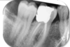
what caused this

Digital (phosphor plate)
- Crescent shaped well defined white mark superimposing the tooth
- Not normal radiographic anatomy
Nail mark

what caused this

Film
- Crescent shaped well defined black mark superimposing the root
Nail mark

what receptor damage is on these images (2 types)

Scraped causing scratches (orange)
Delamination (blue)
- Phosphor layer peel away from edge of image
- Mishandling, wet and drying
- Frayed appearance
Same receptor used twice – bad as obvious damage

white line on phosphor plate (digital receptor)

scratch

cracking on phosphor plate (digital receptor) seen as

network of white lines
due to flexing/bending

what can cause phosphor plate image to be lighter on one side?

potential exposure of receptor to visible light before being processed – causing some sensitisation of phosphor crystals – giving it a darker appearance
collimation error effect on image
- x-ray image cut off as x-ray tube not positioned correctly

image uniformity check
QA receptor image quality
step wedge
step wedge
QA of receptor image quality
A step wedge is one type of test object used to check image quality/contrast
- Self-made or provided by manufacturer
Exposed to a normal clinical exposure (e.g. adult mandibular molar periapical) & resulting image is compared to a baseline (receptor underneath, step wedge on top and expose)
- Baseline: “Must be able to differentiate all 6 steps” = undamaged
- Attenuated to different degrees by the different thicknesses of lead
- Carried out regularly (e.g. every morning)
- With digital there are fewer sources of error to effect contrast than with film so may not be done daily, but usually done regularly

how step wedge works
Exposed to a normal clinical exposure (e.g. adult mandibular molar periapical) & resulting image is compared to a baseline (receptor underneath, step wedge on top and expose)
- Baseline: “Must be able to differentiate all 6 steps” = undamaged
- Attenuated to different degrees by the different thicknesses of lead
Carried out regularly (e.g. every morning)
- With digital there are fewer sources of error to effect contrast than with film so may not be done daily, but usually done regularly

what is step wedge
Overlapping layers of lead foil over wooden spatula

QA of clinical image quality
aims
- ensure that radiographs are consistently adequate for diagnostic purposes
Consists of 3 parts
3 parts of QA of clinical image quality
-
Image quality rating
- Grading each image
-
Image quality analysis
- Reviewing images to calculate “success rate” & identify any trends for suboptimal images – seeing if any trends
- Carried out periodically (e.g. every 4 months you review the last 150 images)
-
Reject analysis
- Recording & analysing each unacceptable image
Action must be taken if non-diagnostic images are occurring too frequently or if same issue keeps arising
when does action need taken in regards QA of clinical image quality
Action must be taken if non-diagnostic images are occurring too frequently or if same issue keeps arising
image quality rating
is
grading each image
image quality analysis is
reviewing images to calculate ‘success rate’ and identifying any trends for suboptimal images - seeing if any treand
carried out periodically (e.g. every 4 months you review last 150 images)
reject analysis is
recording and analysing each unacceptable image
Action must be taken if non-diagnostic images are occurring too frequently or if same issue keeps arising
recommended QA system for clinical image quality
2 categories
diagnostically acceptable (‘A’)
diagnostically not acceptable (‘N’)
quality rating for clinical image quality covers
all components of taking an image and ensuring sufficient in answering clinical Q
e.g. widening PDL, root fracture, caries
diagnostically acceptable (‘A’) basis
no errors or minimal errors in either patient preparation, exposure, positioning, image (receptor) processing or image reconstruction and sufficient image quality to answer the clinical Q
diagnostically not acceptable (‘N’) basis
error in either patient preparation, exposure, positioning, image (receptor) processing or image reconstruction which render the image diagnostically unacceptable
target for A digital imaging
not less that 95%
Digital has less chance of errors – development process/fixing not a worry unlike film
targert for A film imaging
not less that 90%
target for N digital imaging
not greater than 5%
target for N film imaging
not greater than 10%
old QA system
replaced in 2020
1 - excellent
2- diagnostically acceptable
3 - unacceptable
what needs to be know to decide if image ‘diagnostically acceptable’?
you must know what the image is supposed to show
- Which tooth/teeth?
- What parts of the tooth/teeth
- What other structures?
- What extent of the pathology?
how can what the image is supposed to show vary?
- The type of radiograph being taken
- The clinical justification for taking it
positioning factors for diagnostically acceptable
need to correct to see correct anatomy
for that type of image
bitewing radiography
needs to show (3)
Show entire crowns of ↑ & ↓ teeth
- Occlusal surface to ACJ and part of roots (no part of crown should be cut off)
Include distal aspect of the fore-standing posterior tooth, & mesial aspect of the last-standing tooth usually 4s to 7s/8s
- May require >1 radiograph
Every approximal surface shown at least once without overlap (where possible)
- May be impossible if crowding
periapical radiograph
needs to show
- Shows entire root
- Shows periapical bone
- Shows crown
if image is positioned correctly
what 4 other factors do they require to be deemed diagnostically acceptable
- adequate contrast
- adequate sharpness
- adequate resolution
- minimal distortion
possible causes of distortion
Caused by receptor bending or not positioned properly against the teeth
what QA rating is this radiograph
to assess for approximal caries

A
- See all crowns of teeth – occlusal to ACJ
- As well as some root and bone levels
- Minimal overlap – see approximal surfaces clearly
what QA grade is this radiograph
to investigate tooth 37 which is TTP

- Whole of crown with filling
- Both roots
- Bone around apices
- More radio dense on mesial apex – sclerosingosteoitis
what causes the white lines on these images

over/incorrect collimation of image (lead window)
reason for collimation
T
- Too large beam (larger than receptor) – unnecessary radiation pt – hence collimation*
- Not aligned properly = part of image cut off*
what QA grade is this
taken to investigate restorability of tooth 46
N
- See filling and secondary caries
- Bone loss/widening at furcation
- But apices of tooth and bone level around them cut off due to collimation
Technically shows none restorable as secondary caries so advanced but as a periapical not showing whole tooth so not acceptable

what QA grade is this radiograph
taken to assess root canal treatment of tooth 46
N
- Both apices not on image (mesial off)
- Bone level cannot assess as missed off
Regardless N as vast amount of damage to receptor – cracking on right, scratch

what QA is this image
taken to investigate tenderness at apical region of 24-25
- Can see entirety of premolars including apices
- Tight to collimation border – hard to tell if widening of PDL or infection
- Image is pale
Borderline N

what QA is this image
taken to investigate tooth 36 which is TTP
- See whole crown, furcation (with bone loss), RCT, apices
- Nearly cut off distal apex
- Hard to assess pathology of this and bone level
- Nearly cut off distal apex
- Grainy image – issue with processing if film, too low exposure (poor contrast, grainy)
Borderline N

fault analysis is concerned with
clinical image rejects
what caused them
fault analysis identifies
faults and explains them so that they can be remedied
fault analysis requires
ability to problem solve is only as good as your knowledge base
6 potential faults on clincal image
- Inadequate contrast
- Unsharp
- Distorted
- Over-collimated
- Receptor marks/damage
(N.B. may be possible to correct if digital)
collimation error a.k.a
cone cutting
3 possible causes of collimation error
- incorrect assembly of receptor holder
- incorrect allignment between X-ray tube and receptor holder
- incorrect orientation of the rectangular collimator (lead window on end of X-ray tube)
incorrect assembly of receptor holder leads to
collimation error
- Intra oral
- Colours – depending on brand and types
- Components need to be assembled correctly
- Ring to line up X-ray tube and see image receptor straight through in middle

incorrect allignment between X-ray tube and receptor holder leads to
collimation error
- Positioning X-ray tube attached to wall to align with ring on holder

incorrect orientation of rectangular collimator leads to
collimation error
lead window on end of X-ray tube wrong way

incorrect image radiodensity leads to
too dark or too light image
- Hard to see details – caries, apical issues

3 potential causes of incorrect image radiodensity
- exposure factors
- developing factors (film only)
- viewing factors
exposure factors that can lead to incorrect image radiodensity
- incorrect exposure settings
- pt tissues too thick
- faulty timer on X-ray unit
developing factors that can lead to incorrect image radiodensity
(film only)
- incorrect duration
- incorrect temperature
- incorect concentration
viewing factors that can lead to incorrect image radiodensity
- inappropriate light source (film)
- e.g. light box broken,
- inappropiate display screen (digital)
- e.g. wrong setting, too old computer system
- excessive environmental light (cannot see proper contrast on image)
how to choose correct exposure
control panel

2 aims of QA
ensure your radiographs are consistently diagnostic & that your patients are not exposed to unnecessary radiation