Extra Oral Views - Lateral Cephalometric Flashcards
principles of extra-oral radiography
- X-ray source outside the patient
- image receptor outside the patient
- digital CCD/CMOS and storage phosphor options
- previously indirect X-ray film used with intensifying screens
- patient positioning critical
- X-ray beam and image receptor related to patient
reference lines and planes
mid-sagittal plane (MSP) (green)
inter-orbital/pupillary line (green)
orbito-meatal line (OM line) = Radiographic Baseline (RBL): outer canthus of eye to centre of EAM (yellow)
Frankfort Plane: superior border EAM to lowest point of infra-orbital rim
- 10º difference between RBL and FP

4 different maxillofacial views
- postero-anterior
- antero-posterior
- orbitomeatal (line) and occipitomental (view)
- submentovertex
PA
postero-anterior (beam direction)
AP
antero-posterior
OM
orbitomeatal (line) and occipitomental (view)
back of head to chin
SMV
submentovertex (view)
underneath chin to top of head
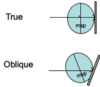
2 types of lateral radiography
true
oblique

true lateral radiography
film and MSP are parallel and X-ray beam is perpendicular to both

Oblique lateral radiograohy
film and MSP are not parallel
X-ray beam is not perpendiculat to either, but oblique to both
less used
3 lateral views
- Lateral cephalometric radiograph (Lateral ceph.)
- Lateral Oblique (mandible) (LOJ) only one side of pt
- Bimolar (both sides on one receptor)
rods position in lateral cephalometric view
rods in EAM

rods position in PA cephalometric views
rods in EAM still
but pt facing image receptor - turn 90o

cephalometric radiography
- Standardised and reproducible form of skull/facial bones radiography
- Used extensively in orthodontics
- lateral and PA projections
- Orthognathic surgery – replaced by CBCT*
- (Implants, but largely replaced by cone beam CT)*
lateral cephalometric radiography
True lateral view of facial bones, base of skull and upper cervical spine.
Also shows paranasal sinuses and nasopharyngeal soft tissues
- Whole mandible, base of skull – how the relate
- Soft tissue – nose, lips, chin
- Scale
- Upper cervical spine
- Sinus – maxillary , sphenoid and ethmoid
- Pharyngeal soft tissue – posterior border and upper surface of tongue, soft palate

guidelines for orthodontic radiographs
BOS Orthodontic Radiographs Guidelines, 2008 & 2015
updated in 4th re CBCT indications
ISBN 1 899297 09 X
Ref. to CBCT in 2008, Full section in 2015
pdf available on-line:

cephs for who?
(4)
- patients with skeletal vertical or antero-posterior discrepancy – judged clinically prior
- requiring fixed or functional appliance therapy, for labio-lingual movement of incisors
- requiring orthognathic surgery in addition to orthodontics (if doing CBCT, don’t do both)
Flow charts pp 20 and 21 (pre-treatment) – unchanged in 2015 since previous edition (10-18years or above and below)

2 indications for lateral cephalometry
Orthognathic Surgery
- Pre-op assessment and post-op review
- Neurovasxular canals
- How bones moved - success
Implant planning - historically
- Anterior mandible - cross sectional image – implant should go through symphysis but actually crosses in – causing bother as alignment wrong
Both of these often superseded if cone beam CT available
cephalometric analysis
- often traced or digitised
- reference lines and planes
- direct digital techniques now available

equipment for ceph
- direct or indirect digital film in casette
- distances
- nasion marker
- magnification scale
- automatic facial contour in direct digital machines (soft tissue)
- heigh and width adjustment
- thyroid collar
direct or indirect digital film in cassette
for lat cephs
Cephalostat (free-standing or attached to panoramic machine)
- ear rods
- CCD/CMOS sensor or cassette holder (phosphor plate or intensifying screens)
- Historic - anti-scatter grid - but higher dose to patient – don’t need increased detail so not justified - not at GDH&S

distances
for lat ceph
Source to patient’s MSP - 152.4cm (5 feet) in traditional equipment
Image receptor to MSP – manufacturer dependent, fixed or adjustable
- in GDH&S fixed
distance from source to pt MSP in lat ceph
152.4cm (5 feet) in traditional equipment
image receptor to MSP distance in lat cep
manufacturer dependent
can be fixed or adjustable
in GDH&S it is fixed


