The OSI Reference Model Flashcards
Commonly referred to as the OSI model or the OSI stack. This seven-layer model categorizes various network technologies.
Open Systems Interconnection (OSI) reference model
The name given to data at different layers of the OSI model. Specifically, the PDU for Layer 4 is segment. The Layer 3 PDU is packet, the Layer 2 PDU is frame, and the Layer 1 PDU is bit.
protocol data unit (PDU)
(data service unit)

One way to electrically or optically represent a binary 1 or 0 is to use current state modulation, which represents a binary 1 with the presence of voltage (on a copper cable) or the presence of light (on a fiber-optic cable). Similarly, the absence of light or voltage represents a binary 0.
current state modulation
(Layer 1 - The Physical Layer)

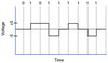
One way to electrically or optically represent a binary 1 or 0 is to use the transition between a voltage level (for example, going from a state of no voltage to a state of voltage, or vice versa, on a copper cable) or the transition of having light or no light on a fiber-optic cable to represent a binary 1. Similarly, a binary 0 is represented by having no transition in a voltage level or light level from one time period to the next. This approach of representing binary digits is called state transition modulation.
state transition modulation
(Layer 1 - The Physical Layer)

A mathematical algorithm that is executed on a data string by both the sender and the receiver of the data string. If the calculated CRC values match, the receiver can conclude that the data string was not corrupted during transmission.
cyclic redundancy check (CRC)
Layer 1 of the OSI model. This layer is concerned with the transmission of bits on a network.
Examples of devices defined by Layer 1 standards include hubs, wireless access points, and network cabling.
physical layer
Layer 1 devices view a network as a physical topology (as opposed to a logical topology).

As Layer 2 of the OSI model, this layer is concerned with the packaging of data into frames and transmitting those frames on a network, performing error detection/correction, uniquely identifying network devices with an address (MAC or LLC), and handling flow control.
data link layer
Layer 2 devices view a network as a logical topology.
Examples of devices defined by data link layer standards include switches, bridges, and NICs.

Layer 3 of the OSI model. This layer is primarily concerned with forwarding data based on logical addresses.
network layer
Examples of devices found at the network layer include routers and multilayer switches. The most common Layer 3 protocol in use, and the protocol on which the Internet is based, is IPv4. However, IPv6 is beginning to be more common on networks today.

As Layer 4 of the OSI model, it acts as a dividing line between the upper layers and the lower layers. Specifically, messages are taken from the upper layers (Layers 5–7) and encapsulated into segments for transmission to the lower layers (Layers 1–3). Similarly, data streams coming from lower layers are decapsulated and sent to Layer 5 (the session layer) or some other upper layer, depending on the protocol.

transport layer (OSI model)
In addition to TCP and UDP, Internet Control Message Protocol (ICMP) is another transport layer protocol you are likely to meet. ICMP is used by utilities such as ping and traceroute, which are discussed in Lesson 10,”Command-Line Tools.”

As Layer 5 of the OSI model, it’s responsible for setting up, maintaining, and tearing down sessions.
session layer

Layer 6 of the OSI model. This layer is responsible for the formatting of data being exchanged and securing the data with encryption.
presentation layer

Layer 7 of the OSI model. This layer provides application services to a network. An important yet often-misunderstood concept is that end-user applications do not reside at the application layer. Instead, the application layer supports services used by end-user applications. Another function of the application layer is advertising available services.
application layer (OSI model)
Recall that even though the application layer is numbered as Layer 7, it is at the top of the OSI stack because its networking functions are closest to the end user.

The network interface layer of the TCP/IP stack (also known as the network access layer) encompasses the technologies addressed by Layers 1 and 2 (that is, the physical and data link layers) of the OSI model.
network interface layer
This layer of the TCP/IP stack maps to Layer 3 (network layer) of the OSI model. Although multiple routed protocols (for example, IPv4 and IPv6) may reside at the OSI model’s network layer, the Internet layer of the TCP/IP stack focuses on IP as the protocol to be routed through a network.
Internet layer
The transport layer of the TCP/IP stack maps to Layer 4 (transport layer) of the OSI model. The two primary protocols found at the TCP/IP stack’s transport layer are TCP and UDP.
transport layer (TCP/IP stack)
Addresses concepts described by Layers 5, 6, and 7 (that is, the session, presentation, and application layers) of the OSI model.
application layer (TCP/IP stack)
Supports different communication sessions (for example, different telephone conversations in a telephony network) on the same physical medium by allowing sessions to take turns. For a brief period of time, defined as a time slot, data from the first session is sent, followed by data from the second session. This continues until all sessions have had a turn, and the process repeats itself.
time-division multiplexing (TDM)
A connection-oriented transport protocol. Connection-oriented transport protocols provide reliable transport, in that if a segment is dropped, the sender can detect that drop and retransmit that dropped segment. Specifically, a receiver acknowledges segments that it receives. Based on those acknowledgments, a sender can determine which segments were successfully received.
Transmission Control Protocol (TCP)
A connectionless transport protocol. Connectionless transport protocols provide unreliable transport, in that if a segment is dropped, the sender is unaware of the drop, and no retransmission occurs.
User Datagram Protocol (UDP)
Also known as the DoD model, this four-layer model (as opposed to the seven-layer OSI model) targets the suite of TCP/IP protocols.
TCP/IP stack
As previously described, the OSI model consists of seven layers:
All People Seem To Need Data Processing
or
Please Do Not Throw Sausage Pizza Away
Layer 1: The physical layer
Layer 2: The data link layer
Layer 3: The network layer
Layer 4: The transport layer
Layer 5: The session layer
Layer 6: The presentation layer
Layer 7: The application layer

Layer 1 PDU
bit (binary)
Layer 2 PDU
frame
Layer 3 PDU
packet
Layer 4 PDU
segment
Bacon Frying Produces Salivation
Bits
Frames, Packets
Packets, Datagrams
Segments, Packets

For two networked devices to successfully communicate at the physical layer, they must agree on when one bit stops and another bit starts. Specifically, the devices need a method to synchronize the bits. Two basic approaches to bit synchronization include asynchronous and synchronous synchronization:
Synchronizing bits
With this approach, a sender states that it is about to start transmitting by sending a start bit to the receiver. When the receiver sees this, it starts its own internal clock to measure the next bits. After the sender transmits its data, it sends a stop bit to say that it has finished its transmission.
Asynchronous
This approach synchronizes the internal clocks of both the sender and the receiver to ensure that they agree on when bits begin and end. A common approach to make this synchronization happen is to use an external clock (for example, a clock given by a service provider). The sender and receiver then reference this external clock.
Synchronous
_______ technologies divide the bandwidth available on a medium (for example, copper or fiber-optic cabling) into different channels. A sender can then transmit different communication streams over the various channels. For example, consider frequency-division multiplexing (FDM) used by a cable modem. Specifically, a cable modem uses certain ranges of frequencies on the cable coming into your home from the local cable company to carry incoming data, another range of frequencies for outgoing data, and several other frequency ranges for various TV stations.
Broadband
_____ technologies, in contrast, use all the available frequencies on a medium to send data. Ethernet is an example of a networking technology that uses _____.
Baseband
_____ allows multiple communications sessions to share the same physical medium. Cable TV, as previously mentioned, allows you to receive multiple channels over a single physical medium (for example, a coaxial cable plugged into the back of your television).
Multiplexing
A downside to TDM is that each communication session receives its own time slot, even if one of the sessions does not have any data to send at the moment. To make a more efficient use of available bandwidth, _____ dynamically assigns time slots to communications sessions on an as-needed basis.
Statistical time-division multiplexing (StatTDM)
_____ divides a medium’s frequency range into channels, and different communication sessions send their data over different channels. As previously described, this approach to bandwidth usage is called broadband.
Frequency-division multiplexing (FDM)
Physical addressing: A common example of a Layer 2 address is a _____, which is a 48-bit address assigned to a device’s network interface card (NIC). _____ are written in hexadecimal notation (for example, 58:55:ca:eb:27:83). The first 24 bits of the 48-bit address is the vendor code. The IEEE Registration Authority assigns a manufacturer one or more unique vendor codes. You can use the list of vendor codes at http://standards.ieee.org/develop/regauth/oui/oui.txt to identify the manufacturer of a networking device, based on the first half of the device’s _____. The last 24 bits of a _____ are assigned by the manufacturer, and they act as a serial number for the device. No two _____ in the world should have the same value.
Logical topology: Layer 2 devices view a network as a logical topology. Examples of a logical topology include bus and ring topologies, as described in Lesson 1.
Method of transmitting on the media: With several devices connected to a network, there needs to be some strategy for deciding when a device sends on the media. Otherwise, multiple devices might send at the same time and thus interfere with one another’s transmissions.
Characteristics of the Media Access Control (MAC)
When a device on a network receives a message from another device on the network, that recipient device can give feedback to the sender in the form of an acknowledgment message.
Connection services
(Characteristics of the Logical Link Control (LLC) sublayer)
Limits the amount of data a sender can send at one time; this prevents the sender from overwhelming the receiver with too much information.
Flow control
(Connection services)
Allows the recipient of data to let the sender know whether the expected data frame was not received or whether it was received but is corrupted. The recipient figures out whether the data frame is corrupt by mathematically calculating a checksum of the data received. If the calculated checksum does not match the checksum received with the data frame, the recipient of the data draws the conclusion that the data frame is corrupted and can then notify the sender via an acknowledgment message.
Error control
(Connection services)
Senders and receivers of data frames need to coordinate when a data frame is being transmitted and should be received.
Synchronizing transmissions
(Characteristics of the Logical Link Control (LLC) sublayer)
With _____ transmission, network devices look to a common device in the network as a clock source, which creates fixed-length time slots. Network devices can determine how much free space, if any, is available within a time slot and then insert data into an available time slot. A time slot can accommodate more than one data frame. _____ transmission does not need to provide clocking at the beginning of a data string (as does synchronous transmission) or for every data frame (as does asynchronous transmission). As a result, _____ transmission uses little overhead when compared to asynchronous or synchronous transmission methods.
Isochronous
(Synchronizing transmissions)
With _____ transmission, network devices reference their own internal clocks, and network devices do not need to synchronize their clocks. Instead, the sender places a start bit at the beginning of each data frame and a stop bit at the end of each data frame. These start and stop bits tell the receiver when to monitor the medium for the presence of bits.
An additional bit, called the parity bit, might also be added to the end of each byte in a frame to detect an error in the frame. For example, if even parity error detection (as opposed to odd parity error detection) is used, the parity bit (with a value of either 0 or 1) would be added to the end of a byte, causing the total number of 1s in the data frame to be an even number. If the receiver of a byte is configured for even parity error detection and receives a byte where the total number of bits (including the parity bit) is even, the receiver can conclude that the byte was not corrupted during transmission.
Using a parity bit to detect errors might not be effective if a byte has more than one error (that is, more than one bit that has been changed from its original value).
asynchronous
With _____ transmission, two network devices that want to communicate between themselves must agree on a clocking method to show the beginning and ending of data frames. One approach to providing this clocking is to use a separate communications channel over which a clock signal is sent. Another approach relies on specific bit combinations or control characters to indicate the beginning of a frame or a byte of data.
Like asynchronous transmissions, _____ transmissions can perform error detection. However, rather than using parity bits, _____ communication runs a mathematical algorithm on the data to create a cyclic redundancy check (CRC). If both the sender and the receiver calculate the same CRC value for the same chunk of data, the receiver can conclude that the data was not corrupted during transmission.
synchronous
Whereas the data link layer uses physical addresses to make forwarding decisions, the network layer uses _____ to make forwarding decisions. A variety of routed protocols (for example, AppleTalk and IPX) have their own _____ schemes, but by far, the most widely deployed routed protocol is Internet Protocol (IP).
logical addressing
Engineers often associate the term _____ with Layer 2 technologies; however, the concept of _____ also exists at Layer 3. _____, at its essence, is making decisions about how data should be forwarded. At Layer 3, three common _____ techniques exist:
switching
With _____, a data stream is divided into packets. Each packet has a Layer 3 header that includes a source and destination Layer 3 address. Another term for _____ is routing, which is discussed in more detail in Lesson 6,”Routing IP Packets.”
packet switching
_____ dynamically brings up a dedicated communication link between two parties for those parties to communicate.
As a simple example of _____, think of making a phone call from your home to a business. Assuming you have a traditional landline servicing your phone, the telephone company’s switching equipment interconnects your home phone with the phone system of the business you are calling. This interconnection (that is, circuit) only exists for the duration of the phone call.
Circuit switching
Unlike packet switching and circuit switching technologies, _____ is usually not well suited for real-time applications because of the delay involved. Specifically, with message switching, a data stream is divided into messages. Each message is tagged with a destination address, and the messages travel from one network device to another network device on the way to their destination. Because these devices might briefly store the messages before forwarding them, a network using message switching is sometimes called a store-and-forward network. Metaphorically, you could visualize message switching like routing an email message, where the email message might be briefly stored on an email server before being forwarded to the recipient.
Message switching
TCP communication uses _____, in that one or more segments are sent at one time, and a receiver can attest to the receipt of all the segments in a window with a single acknowledgment. In some cases, as illustrated in Figure 2-11, TCP uses a sliding window, where the window size begins with one segment. If there is a successful acknowledgment of that one segment (that is, the receiver sends an acknowledgment asking for the next segment), the window size doubles to two segments. Upon successful receipt of those two segments, the next window holds four segments. This exponential increase in window size continues until the receiver does not acknowledge successful receipt of all segments within a certain amount of time—known as the round-trip time (RTT), which is sometimes called real transfer time—or until a configured maximum window size is reached.
windowing
(Layer 4)

With _____, a device (for example, a router) uses a chunk of memory (sometimes called a _____ or a queue) to store segments if bandwidth is not available to send those segments. A queue has a finite capacity, however, and can overflow (that is, drop segments) in case of sustained network congestion.
buffering
Checking user credentials (for example, username and password)
Assigning numbers to a _____ communication flows to uniquely find each one
Negotiating services needed during the _____
Negotiating which device begins sending data
Setting up a session: Examples of the procedures involved in setting up a session include the following:
Transferring data
Reestablishing a disconnected session
Acknowledging receipt of data
Maintaining a session: Examples of the procedures involved in supporting a session include the following:
A session can be disconnected based on agreement of the devices in the session. Alternatively, a session might be torn down because one party disconnects (either intentionally or because of an error condition). If one party disconnects, the other party can detect a loss of communication with that party and tear down its side of the session.
Tearing down a session

Explanation: Here are the seven OSI Layers and their functions:
Physical Layer: Transmits bits on the network with network characteristics. It also defines how to represent bits on the medium and wiring standards for connectors and jacks.
Data Link Layer: Packages data into frames and then transmits them on the network. It also performs error detection/correction and handles flow control.
Network Layer: Forwards data on the basis of logical addresses. It also performs route discovery and selection.
Transport Layer: Encapsulates and decapsulates messages sent between upper and lower layers. TCP and UDP are the two common protocols at this layer.
Session Layer: Sets up, maintains, and ends sessions. H.323 is an example of a session layer protocol, which can help set up, support, and tear down a voice or video connection.
Presentation Layer: Formats the data being exchanged and secures that data by encryption. This ensures that a third party would not be able to unscramble or decrypt the data.
Application Layer: Provides support for services used by an end-user. It also advertises available services.


Explanation: The most widely deployed routed protocol at the Network Layer of the OSI model is IP. The connectionless protocol at the Transport Layer of the OSI model is UDP, which offers unreliable data transfer. Whereas, TCP is a connection-oriented protocol at the Transport Layer of the OSI model that offers reliable transport, in that if a segment is dropped, the sender can detect that drop and retransmit the dropped segment.

The TCP/IP stack has only four defined layers, as opposed to the seven layers of the OSI model. Figure 2-15 contrasts these two models for an illustrative understanding.
Layers of the TCP/IP Stack

The TCP/IP stack’s _____ layer encompasses the technologies offered by Layers 1 and 2 (the physical and data link layers) of the OSI model.
network interface
The _____ layer of the TCP/IP stack maps to Layer 3 (the network layer) of the OSI model. Although multiple routed protocols (for example, IP, IPX, and AppleTalk) live at the OSI model’s network layer, the Internet layer of the TCP/IP stack focuses on IP as the protocol to be routed through a network. Figure 2-16 shows the format of an IP Version 4 packet.
Internet
Notice that there are fields in the IP packet header for both a source and a destination IP address. The Protocol field shows the transport layer protocol from which the packet was sent or to which the packet should be sent. Also of note is the Time-to-Live (TTL) field. The value in this field is decremented by 1 every time this packet is routed from one IP network to another (that is, passes through a router). If the TTL value ever reaches 0, the packet is discarded from the network. This behavior helps prevent routing loops. As a common practice, the OSI layer numbers of 1, 2, and 3 are still used when referring to physical, data link, and network layers of the TCP/IP stack, even though the TCP/IP stack does not explicitly separate the physical and data link layers.

The _____ of the TCP/IP stack maps to Layer 4 (the transport layer) of the OSI model. The two primary protocols found at the TCP/IP stack’s transport layer are TCP and UDP.
transport layer
Also notice the field for window size. The value in this field determines how many bytes a device can receive before expecting an acknowledgment. As previously described, this feature offers flow control.
The header of a TCP segment also contains sequence numbers for segments. With sequence numbering, if segments arrive out of order, the recipient can put them back in the proper order based on these sequence numbers.
The acknowledgment number in the header shows the next sequence number the receiver expects to receive. This is a way for the receiver to let the sender know that all segments up to and including that point have been received. Due to the sequencing and acknowledgements, TCP is considered to be a connection-oriented transport layer protocol.

_____ is a connectionless, unreliable protocol. ____ lacks the sequence numbering, window size, and acknowledgment numbering present in the header of a TCP segment. The _____ segment’s header simply contains source and destination port numbers, a _____ checksum (which is an optional field used to detect transmission errors), and the segment length (measured in bytes).
UDP
Because a UDP header is so much smaller than a TCP header, UDP becomes a good candidate for the transport layer protocol for applications that need to maximize bandwidth and do not require acknowledgments (for example, audio or video streams).

The biggest difference between the TCP/IP stack and the OSI model is found at the TCP/IP stack’s _____ layer. This layer addresses concepts described by Layers 5, 6, and 7 (the session, presentation, and application layers) of the OSI model.
Application
In computer networking, _____ is a method of designing modular communication protocols in which logically separate functions in the network are abstracted from their underlying structures by inclusion or information hiding within higher level objects.
The process of putting headers (and sometimes trailers) around some data.
encapsulation

Example: Port Numbers and IP Addresses
Notice that when the web server sends content back, the IP addresses and port numbers have now switched, with the web server as the source and your PC as the destination. With both source and destination port numbers, along with source and destination IP addresses, two-way communication becomes possible.
DHCP
Dynamic Host Configuration Protocol: Dynamically assigns IP address information (for example, IP address, subnet mask, DNS server’s IP address, and default gateway’s IP address) to a network device
DNS
Domain Name System: Resolves domain names to corresponding IP addresses
FTP
File Transfer Protocol: Transfers files with a remote host (typically requires authentication of user credentials)
H.323
A signaling protocol that provides multimedia communications over a network
HTTP
Hypertext Transfer Protocol: Retrieves content from a web server
HTTPS
Hypertext Transfer Protocol Secure: Used to securely retrieve content from a web server
IMAP
Internet Message Access Protocol: Retrieves email from an email server
IMAP4
Internet Message Access Protocol Version 4: Retrieves email from an email server
LDAP
Lightweight Directory Access Protocol: Provides directory services (for example, a user directory that includes username, password, email, and phone number information) to network clients
LDAPS
Lightweight Directory Access Protocol over SSH: A secured version of LDAP
MGCP
Media Gateway Control Protocol: Used as a call control and communication protocol for Voice over IP networks
NetBIOS
Network Basic Input/Output System: Provides network communication services for LANs that use NetBIOS
NNTP
Network News Transport Protocol: Supports the posting and reading of articles on Usenet news servers
NTP
Network Time Protocol: Used by a network device to synchronize its clock with a time server (NTP server)
POP3
Post Office Protocol Version 3: Retrieves email from an email server
RDP
Remote Desktop Protocol: A Microsoft protocol that allows a user to view and control the desktop of a remote computer
rsh
Remote Shell: Allows commands to be executed on a computer from a remote user
RTP
Real-time Transport Protocol: Used for delivering media-based data (such as Voice over IP) through the network
RTSP
Real-Time Streaming Protocol: Communicates with a media server (for example, a video server) and controls the playback of the server’s media files
SCP
Secure Copy: Provides a secure file-transfer service over an SSH connection and offers a file’s original date and time information, which is not available with FTP
SFTP
Secure FTP: Provides FTP file-transfer service over an SSH connection
SIP
Session Initiation Protocol: Used to create and end sessions for one or more media connections, including Voice over IP calls
SMB
Server Message Block: Used to share files, printers, and other network resources
SMTP
Simple Mail Transfer Protocol: Used for sending email
SNMP
Simple Network Management Protocol: Used to monitor and manage network devices
SNMP Trap
Simple Network Management Protocol Trap: A notification sent from an SNMP agent to an SNMP manager
SNTP
Simple Network Time Protocol: Supports time synchronization among network devices, similar to Network Time Protocol (NTP), although SNTP uses a less complex algorithm in its calculation and is slightly less accurate than NTP
SSH
Secure Shell: Used to securely connect to a remote host (typically via a terminal emulator)
Telnet
Telnet: Used to connect to a remote host (typically via a terminal emulator)
TFTP
Trivial File Transfer Protocol: Transfers files with a remote host (does not require authentication of user credentials)

Explanation: Here are the TCP/IP layers:

Network interface: This layer encompasses the technologies addressed by Layers 1 and 2 (physical and data link layers) of the OSI model. The Network interface layer defines how data is physically sent through the network.
Internet: This layer maps to Layer 3 (the network layer) of the OSI model. The Internet layer performs IP routing.
Transport: This layer maps to Layer 4 (the transport layer) of the OSI model. The Transport layer manages communication sessions between host computers.
Application: This layer addresses concepts described by Layers 5, 6, and 7 (the session, presentation, and application layers) of the OSI model. The Application layer defines how host programs interface with the transport layer services to use the network

Explanation: Here are the application layer protocols:

Protocol Description
TFTP - Transfers files with a remote host without requiring user authentication
IMAP - Retrieves e-mail from an e-mail server
SMB - Used to share files, printers, and other network resources over a network
SFTP - Provides secure file-transfer over an SSH connection
HTTP - Retrieves contents from a web server
RDP - Allows a user to view and control the desktop of a remote computer


Summary
Here are the main topics covered in this lesson:
The ISO’s OSI reference model consists of seven layers: physical (Layer 1), data link (Layer 2), network (Layer 3), transport (Layer 4), session (Layer 5), presentation (Layer 6), and application (Layer 7). The purpose of each layer was presented, along with examples of technologies living at the individual layers, as it pertains to networking.
The TCP/IP stack was presented as an alternative model to the OSI reference model. The TCP/IP stack consists of four layers: network interface, Internet, transport, and application. These layers were compared with the seven layers of the OSI model.
This lesson discussed how port numbers are used to associate data at the transport layer with a proper application layer protocol. Examples of common application layer protocols in the TCP/IP suite were presented, along with their port numbers.


