System Components Flashcards
(118 cards)
Form Factors
Motherboards adhere to design specifications called form factors. The form factor determines the physical characteristics of a motherboard, including its dimensions, number of expansion slots, and mounting hole locations, as well as the back panel dimensions, arrangement, and orientation.
ATX
The ATX (advanced technology extended) form factor is the most commonly used form factor. Because of its popularity, several variants of the ATX form factor exist. Each variant has different specifications for dimensions and number of expansion slots. However, all ATX variants share the following characteristics:
- Back plate measurements (6.25” × 1.75”)
- Power supply specifications:
- 24-pin ATX power connector
- On/off switch runs from the case to the motherboard
- Soft-power control (OS can turn the computer off)
- Expansion slot locations and spacing (0.8” between slots)
- Mounting hole locations
- CPU location (top of board near power supply)
Standard ATX
The standard ATX form factor is the form factor that all other variants are modeled after. ATX motherboards:
- Measure 12” × 9.6”
- Have up to seven expansion slots
- Have between six and nine mounting holes
Extended ATX
(EATX)
The EATX form factor is the largest ATX variant. EATX:
- Measures 12” × 13”
- Typically uses extra space for additional memory slots
microATX
The microATX form factor is a smaller version of the ATX form factor. The microATX form factor:
- Measures 9.6” × 9.6”
- Has four expansion slots
ITX
The ITX form factor was designed for low-power, small form factor (SFF) computers. The most common ITX form factor is the Mini-ITX form factor. The Mini-ITX form factor:
- Specifies a maximum motherboard size of 6.7” × 6.7”
- Has only one expansion slot
- Allows for small (100 watt) power supplies
- Is typically used with a home theater PC (HTPC)
Other ITX form factors include the following:
- Nano-ITX (4.7” × 4.7”)
- Pico-ITX (3.9” × 2.85”)
- Mobile-ITX (2.9” × 1.7”)
The Mini-ITX form factor uses the same mounting locations and back panel specifications as the ATX form factor, allowing Mini-ITX motherboards to fit in ATX cases.
BTX
The BTX (balanced technology extended) form factor was designed as a replacement for the ATX form factor. However, it did not gain widespread adoption. With BTX:
- The CPU is positioned in such a way that air flow is increased.
- There is no heatsink fan. Instead, a thermal module or shroud fits over the CPU to move heat directly out of the system.
- The back panel orientation and mounting location is reversed.
BTX was implemented mainly by computer manufacturers such as Dell
ATX Full-tower
ATX full-tower cases are the largest computer cases. Full-tower cases have a lot of space for external and internal components. ATX full-tower cases are compatible with the following form factors:
- Standard ATX
- EATX
- microATX
ATX Mid-tower
ATX mid-tower cases are slightly smaller than full-tower cases. Mid-tower cases have fewer external and internal bays. ATX mid-tower cases are compatible with the following form factors:
- Standard ATX
- microATX
- Mini-ITX
- EATX (some)
microATX Tower
microATX towers are smaller cases designed to be placed on desktops. microATX towers typically have only one drive bay and are compatible with the following form factors:
- microATX
- Mini-ITX
Some microATX towers have a slim design. These cases are typically half the width of a microATX tower and are designed to lie flat or upright.
Mini-ITX Tower
Mini-ITX towers are designed to house mini-ITX motherboards. They are typically smaller than microATX towers.
HTPC
Home theatre PC (HTPC) cases are designed to connect to TVs and be used as a home media computer. HTPC cases are compatible with microATX and Mini-ITX form factors.
Notebook
Notebook cases are generally proprietary and often vary among models.
When you purchase a computer case, it will usually come with the following components:
- Computer case
- Power supply (although the power supply might also be separate)
- Case fans
- Plastic or rubber feet that attach to the bottom of the case
- Metal screws and standoffs for attaching the motherboard
- Additional external connectors (such as audio, USB, and FireWire) that connect to motherboard headers
Power supplies perform the following functions:
- Convert AC power to DC power
- AC (alternating current) is the type of current distributed through wall sockets. The voltage alternates between a negative and a positive charge, which is good for appliances requiring a high current.
- DC (direct current) is the type of current used inside a computer. Negative particles are drawn toward a positive charge, creating a unidirectional current flow. This type of predictable reliable current is ideal for an application where a lower current is required.
- Provide components with the correct levels of DC voltage
- Standard ATX power supplies provide + 3.3 volts, +/- 5 volts, and +/- 12 volts of DC power. Most modern components require +12 volt output.
- Each separate voltage output circuit is referred to as a rail and can power multiple devices. To avoid overloading one circuit, many newer power supplies have two or more +12 volt rails. These are known as dual rail power supplies. Separate rails balance the power load between multiple circuits, preventing any one circuit from becoming overloaded.
- Aid in thermal management
- All ATX power supplies have a fan that cools the unit.
- The fan direction pulls cooler air from the front of the case and blows hot air out the back.
Older ATX units use a reverse air flow that blows air directly over the CPU. This method is not as efficient
You should be aware of the following facts about power supplies
- Power supplies should be matched to the motherboard and case form factor (i.e., match an ATX power supply with an ATX motherboard or a microATX power supply with a microATX motherboard).
- Some power supplies have a voltage switch that toggles between two voltage settings. Depending on the country, typically, the voltage switch can be toggled either between 115 and 230 volts, or between 110 and 220 volts.
- 115 volts is used in North America.
- 230 volts is used in Europe.
- 100 volts is used in Japan.
- 220 volts is used in most parts of Asia.
Most modern power supplies eliminate the voltage switch and instead automatically switch between voltages as necessary. These power supplies automatically adjust to accept input voltages in the range of 100 to 240 volts.
- Many power supplies have a switch on the back that turns the power on or off.
- Power supplies are rated in watts. A power supply’s watt rating determines its maximum power output. To determine a computer’s power requirements, use the following method:
- Find the watt requirement for each component by multiplying volts by amps (W = V × A).
- Add each value together to find the total watt requirements.
Alternatively, there are several online tools you can use to estimate a computer’s watt requirements.
- ATX power supplies provide soft power, even when the computer is turned off, the motherboard has power. Soft power allows the computer to be turned on and off by the operating system or over the network.
Name and describe the connector
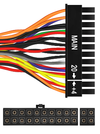
24-pin (20+4 pin) ATX connector
The 24-pin ATX power plug supplies power to the motherboard.
- Some 24-pin connectors have one 20-pin plug and a detachable 4-pin plug. This allows for backwards compatibility with 20-pin motherboards.
- You can plug a 24-pin ATX power plug into a 20-pin motherboard connector, leaving the four pins unconnected.
Older motherboards used 20-pin power plugs. With a 24-pin ATX power plug, the four extra pins supply an additional 3.3, 5, and 12 volts of DC power.
Name and describe the connector

4-pin 12 V (P4) power
Starting with the Pentium 4 (P4) processor, CPUs required more power than could be provided through the ATX power plug. The 4-pin 12 V connector:
- Connects to the motherboard
- Provides two dedicated 12 V wires to the CPU (Older processors only used 5 V power)
The 4-pin 12 V CPU connector is not the same as the 20+4-pin ATX power connector.
Name and describe the connector
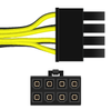
8-pin EPS12V CPU power
Modern processors consume even more power. The 8-pin EPS12V connector provides four lines of 12 V power.
- The 8-pin EPS12V was originally used with some older dual processor systems.
- All modern multi-core processors use this connector.
Some power supplies have two 4-pin connectors (4+4) that are meant to be used side-by-side in the 8-pin plug.
Name and describe the connector
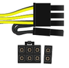
6+2-pin PCIe
Newer video cards require more power than can be supplied through the PCI Express bus. The 6+2-pin PCIe connector plugs directly into the video card to supply additional, dedicated power. The 6+2-pin PCIe:
- Provides up to 150 watts
- Is also known as a PEG6+2 (PCI Express Graphics 6+2 pin)
Some motherboards have only a 6-pin PCIe connector. These connectors provide up to 75 watts.
Name and describe the connector
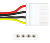
4-pin peripheral power
The 4-pin peripheral power connector (colloquially called a 4-pin Molex connector) is used by legacy components (e.g., IDE hard drives and PATA optical drives), case fans, and other accessory devices. The connector provides both 5 V (red wire) and 12 V (yellow wire).
- Each power supply cable typically has multiple 4-pin connectors on the same cable.
- When connecting devices, try to balance the devices connected to each cable
Name and describe the connector

SATA power
The SATA power connector has 15 pins and provides 3.3, 5, and 12 volts. As its name implies, it powers SATA devices.
- You can use a special adapter to convert a 4-pin peripheral power connector to a SATA connector.
- When using an adapter, or on some power supplies, the connector supplies only 5 and 12 volts.
Name and describe the connector

4-pin mini-Molex
The 4-pin mini-Molex connector provides both 5 and 12 volts and is used by floppy drives.
Most modern power supplies do not have a 4-pin mini-Molex connector.
When troubleshooting a power supply, keep the following in mind
troubleshooting a power supply, keep the following in mind:
- Symptoms of bad power supply include:
- The computer does not turn on
- The computer sporadically shuts off or reboots
- A broken or noisy fan
- Before opening up the computer, rule out the obvious. Make sure:
- The power cord is plugged into the wall.
- The power switch is in the on position.
- The voltage switch is set to the correct voltage.
- Test the power supply using a multimeter or power supply tester. Voltage levels should be within +/- 5% of normal. If they aren’t, the power supply is bad or failing and should be replaced.
- 12 V rail should be between 11.4 and 12.6 volts.
- 5 V rail should be between 4.7 and 5.25 volts.
- 3.3 V rail should be between 3.1 and 3.4 volts.
- Because power supplies carry dangerous levels of electrical current, always take proper safety precautions.
- Never ground yourself when working on a power supply.
- Never open or disassemble a power supply. Always replace the entire unit.
Some computer manufacturers, such as Dell or HP, produce proprietary power supplies. These power supplies might have a unique shape or use different wiring schematics on connectors. When replacing a power supply, identify whether a standard ATX or a proprietary power supply is required.