Pistol Grip Tool (PGT) Flashcards
NASA-EVA Pistol Grip Tool (PGT)

Purpose: This tool is designed for use by astronauts during EVA to apply torque to the Hubble Space Telescope and International Space Station mechanical interfaces and fasteners.

PGTs are some of the most commonly used EVA tools and are used for almost all bolt-driving operations.

Description:
- The PGT is a self-contained, microprocessor controlled, battery powered, 3/8-inch drive handheld tool and non-powered ratchet wrench.
- There are numerous torque, speed, and turn/angle limits that can be programmed into the PGT for use during various mission phases.

PGT COMPONENTS

- ON/OFF SWITCH
- MODE SWITCH
- SPEED COLLAR
- TORQUE COLLAR
- RATCHET COLLAR
- MULTI-SETTING TORQUE LIMITER (MTL)
- TRIGGER
- RS422 PORT
- SOFT TETHER POINTS
- BAYONET FITTING
- PGT BATTERY

PGT IDENTIFICATION (S/N#)
- PGTs are identified by large ID numbers stenciled in the thermal tape on the side and top of the chassis, instead of serial numbers.
- The ID numbers represent the last digit of the serial number. Therefore, PGT s/n 1001 to 1008 have ID numbers of “1” to “8”.

- ON/OFF SWITCH
- MODE SWITCH

- On the back of the PGT body, above the On/Off Switch, is a switch to toggle the PGT torque mode. This works in conjunction with the Torque Collar. The torque collar has seven settings.
- The Mode Switch allows for seven settings in “A” mode and seven additional settings in “B” mode (A1-A7, B1-B7). When operating this switch using the EMU glove it is easy to either inadvertently toggle the On/Off switch or miss the Mode switch entirely.
SPEED COLLAR

- The Speed Collar is the aft-most collar on the PGT body. This collar controls the rotational speed of the PGT output shaft and also provides a setting to perform the calibration procedure. See Calibration.
- The Output Shaft rotates in the clockwise direction for CW settings and counter-clockwise for CCW settings. All speeds are in Revolutions per Minute (RPM). All six (CW1-CW3 & CCW1-CCW3) speed settings are independently programmable. Speeds can be programmed between 5-60 RPM. In practice the CW and CCW speeds are programmed the same.
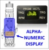
ALPHANUMERIC DISPLAY

The PGT alphanumeric display provides the torque and speed setting, actual torque achieved, turn count, and fault messages. Contents of the display depend on the PGT mode/settings and are software controlled. Decimal values are distinguished by a smaller font. The display will go blank if the PGT exceeds the programmed auto-sleep time.


