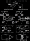
engines and APU Flashcards

1
Q

in the picture what is number 1 ?

A

Total Air Temperature (TAT) indicated in degress C

label - cyan

temperature - white

2
Q

what does number 2 indicate in the picture ?

A

Displayed (green) – the active N1 limit reference mode.

3
Q

in the picture below number 2 indicates the active N1 limit reference mode, in what position does the N1 SET Outer Knob need to be ?

A

in AUTO

page 7.11.2

4
Q

when the pilot sets the N1 SET Outer Knob on either 1,2 or BOTH the thrust mode annunciation on the Thrust Mode Display will be ?

A

MAN (manual)

page 7.11.2

5
Q

what does number 3 indicate on the picture below ?

A

Displayed (green) – selected assumed temperature (degrees C) for reduced thrust takeoff N1.

Repeats data selected on TAKEOFF REF page.

page 7.11.3

6
Q

what does the number 4 in the below picture indicate and when does this come up ?

A

Illuminated (white) – The FMC is not providing the A/T system with N1 limit values.

The A/T is using a degraded N1 thrust limit from the related EEC.

page 7.11.3

7
Q

when the N1 SET Outer Knob is on AUTO where are both reference N1 bugs based on and what is displayed ?

A

both reference N1 bugs are set by FMC based on Limit Page and T/O Page

N1 bugs display A/T N1 limit

page 7.11.3

8
Q

when the N1 SET Outer Knob is on BOTH where are both reference N1 bugs based on ?

A

N1 bugs and readouts are manually set by turning N1 SET Inner Knob

(has no effect on A/T ops)

page 7.11.3

9
Q

when the N1 SET Outer Knob is on 1 or 2, where are both reference N1 bugs based on ?

A

respective N1 reference bug and readout are manually set by turning N1 SET Inner Knob

(has no effect on A/T ops)

page 7.11.3

10
Q

what is the N1 SET Inner Knob used for ?

A

to position reference N1 bug(s) and readouts when N1 SET outer knob is set to BOTH, 1, or 2

page 7.11.4

11
Q

what is the item rappresented by number 3 in the picture ?

A

Position corresponds to digital value on the Reference N1 Readout.

Displayed (green)

page 7.11.4

12
Q

what is the item rappresented by number 4 in the picture ?

A

N1% RPM operating limit

Displayed (red)

page 7.11.4

13
Q

what does the indicate the item rappresented by number 5 in the picture ?

A

difference between actual N1 and value commanded by thrust lever position

Displayed (white)

page 7.11.4

14
Q

what does the item rappresented by number 6 indicate in the picture below ?

A

N1 RPM Digital Readout

(displayed white for normal operating range)

page 7.11.4

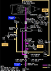
15
Q

what does it mean when the N1 RPM readout (item number 6 on picture) is red and surrunded by a red box ?

A

red - operating limits have been exceeded

red box - on the ground after engine shut down it will indicate an exceeded has occured during flight

page 7.11.4

16
Q

when would the Reference N1 Readout (item number 7 on picture) be displayed ?

A

when N1 SET outer knob is in BOTH, 1, or 2 position to manually set N1 % RPM

displayed green

page 7.11.4

17
Q

what does it mean when the Reference N1 Readout (item n7 on picture) displays “- - - -“

A

N1 SET outer knob is in AUTO position and FMC source invalid.

18
Q

when is the Reference N1 Readout (item n7 on picture) blank ?

A

when N1 SET Outer Knob is in AUTO position

page 7.11.4

19
Q

when is the Thrust Reverser Indication green and when amber ?

A

Displayed (amber) – thrust reverser is moved from stowed position

Displayed (green) – thrust reverser is deployed

page 7.11.4

20
Q

when is the Termal Anti-Ice Indication green and when amber ?

A

Displayed (green) – cowl anti–ice valve(s) open.

Displayed (amber) – cowl anti–ice valve is not in position indicated by related engine anti–ice switch.

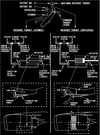
page 7.11.4

21
Q

what does the Exhaust Gas Temperature Redline indicate (n1 on picture) ?

A

maximum T/O EGT limit

page 7.11.6

22
Q

what does the Exhaust Gas Temperature AMber bands indicate (n2 on picture) ?

A

lower end of band displays maximum continuous EGT limit.

23
Q

what does the EGT Start Limit Indicate (n3 on picture) ?

A

Displayed (red) – until the engine achieves stabilized idle (approximately 59% N2)

page 7.11.6

24
Q

what does it mean when the EGT Digital Readout is white ?

A

normal operation range

page 7.11.6

25
Q

what does it mean when the EGT Digital Readout is amber ?

A

maximum continuous limit exceeded

page 7.11.6

26
Q

how many minutes is the color change inhibited from changing from amber to white of the EGT Readout during T/O or G/A ?

A

5 min

page 7.11.6

27
Q

when is the color change inhibited to change from amber to white of the EGT Readout during T/O or G/A extended up to 10 min?

A

during takeoff or go-around when an engine out condition occurs within the first 5 minutes of the inhibit

page 7.11.6

28
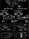
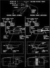
Q

when does the EGT Readout become red ?

A
  • maximum T/O limt exceeded

or

  • start limit exceeded

page 7.11.6

29
Q

after both engines are shut down on the ground what does a red box around the EGT Readout indicate ?

A

an exceedance has occurred

page 7.11.6

30
Q

what does it mean when the EGT Readout is white-blinking ?

A

EEC senses conditions that may lead to hot start or stall during ground starting

page 7.11.6

31
Q

what does the EGT indication white colour indicate ?

A

normal operation range

page 7.11.6

32
Q

when does the EGT indication become amber ?

A

when maximum continuous limit has been exceeded

page 7.11.6

33
Q

how many minutes is the color change inhibited from changing from amber to white of the EGT Indication during T/O or G/A ?

A

5 min

page 7.11.6

34
Q

when is the color change inhibited to change from amber to white of the EGT Indication during T/O or G/A extended up to 10 min?

A

during takeoff or go–around when an engine out condition occurs within the first 5 minutes of the inhibit

page 7.11.6

35
Q

when does the EGT Indication become red ?

A
  • maximum T/O limit exceeded

or

  • start limit exceeded

page 7.11.6

36
Q

when does the ENG FAIL Amber Indication come on ?

A
  • engine operating below sustainable idle (less than 50% N2)

and

  • engine start lever in IDLE position.

page 7.11.6

37
Q

how long does the ENG FAIL Amber Indication alert remains ?

A

until:

  • engine recovers

or

  • start lever moved to CUTOFF

or

  • engine fire warning switch pulled.

page 7.11.7

38
Q

when does the START VALVE OPEN Alert illuminate steady amber and when amber-blinking ?

A

steady – respective engine start valve open and air is supplied to starter

blinking – uncommanded opening of start valve

page 7.11.7

39
Q

when does the LOW OIL PRESSURE Alert illuminate steady amber and when amber-blinking ?

A

steady – oil pressure at or below red line

blinking – with a condition of low oil pressure.

page 7.11.8

40
Q

when does the OIL FILTER BYPASS Alert illuminate steady amber and when amber-blinking ?

A

steady – indicates an impending bypass of scavenge oil filter

blinking – with an impending bypass.

page 7.11.8

41
Q

when is the amber-blinking of the START VALVE OPEN, LOW OIL PRESSURE, OIL FILTER BYPASS alerts is inhibited ?

A
  • during takeoff from 80 knots to 400 feet RA, or 30 seconds after reaching 80 knots, whichever occurs first
  • during landing below 200 feet RA until 30 seconds after touchdown
  • during periods when blinking is inhibited (alerts illuminate steady)

page 7.11.8

42
Q

when are the Secondary Engine Indications dispalyed ?

A
  • when CDS initially receives power
  • when selected by the Multi-Function Display (MFD)
  • in flight when an engine start lever moved to CUTOFF
  • in flight when an engine fails
  • when a secondary engine parameter exceeds normal operating range.

page 7.11.9

43
Q

what does the N2 redline indicate ?

A

N2% operating limit

page 7.11.10

44
Q

what does it mean when the N2 RPM Indications (n2 on picture) is white or red ?

A

white - normal ops range

red - operating limit exceeded

page 7.11.10

45
Q

what does it mean when the N1 Digital Readout is white, red or with red box around ?

A

white - normal ops range

red - operting limit exceeded

red box around on the ground after engine shut down - indicates a inflight exceedance has occurred

page 7.11.10

46
Q

when does the X-BLEED Indication come on and what is it for?

A

cross bleed air raccomended for inflight start

displayed when airspeed is less than required for a windmilling start

page 7.11.10

47
Q

what does RATE indicate on the Fuel Flow Switch ?

A

fuel flow to engine

page 7.11.11

48
Q

what will be displayed when you elect USED on the Fuel Flow switch ?

A

fuel used since last reset

(after 10 sec reverts to RATE automatically)

page 7.11.11

49
Q

what does the RESET do on the Fuel Flow switch ?

A

resets fuel used to ZERO

page 7.11.11

50
Q

is the fuel flow displayed a KG figure or a LTR figure ?

A

KG x 1000

page 7.11.11

51
Q

regarding the OIl PRESS Readout and Pointer explain the white, amber and red colour ?

A

white - normal ops range

amber - caution range

red - operating limit reached

page 7.11.12

52
Q

the pointer will fall into the Low Oil Pressure Amber Band when a low oil pressure situation is detected, what is the minim N2 % RPM for it to be dislayed ?

A

65% N2

page 7.11.12

53
Q

regarding the OIL TEMP Readout and Pointer explain the white, amber and red colour ?

A

white - normal ops range

amber - caution range reached

red - operating limit reached

page 7.11.13

54
Q

what happens when you turn the ENGINE START switch to GRD ?

A
  • opens start valve
  • closes engine bleed valve
  • arms igniters
  • releases to OFF at start valve cut out

page 7.15.1

55
Q

is there any difference between igniters selection when the Engine Start switch in on GRD is selected on ground or in flight ?

A

yes

ground start - selected igniter/igniters (engine start lever IDLE)

inflight start - selectes BOTH igniters (engine start lever IDLE)

page 7.15.1

56
Q

what happens when you turn the ENGINE START Switch to OFF ?

A

ignition OFF - this is the normal position

page 7.15.1

57
Q

with the ENGINE START Switch OFF the ignition is OFF, is there a case when the igniters are activated ?

A

Engine Start Lever on IDLE igniters are activated when:

  • uncommanded rapid N2 RPM decrease
  • N2 between 57% - 50%
  • in flight N2 between idle and 5%

page 7.15.1

58
Q

what does the CONT option of the Engine Start Switch do, on the ground and in flight ?

A

ground - provides ignition to selected igniters (start lever has to be on IDLE)

in flight - provides ignition of both igniters when N2 is below IDLE (start lever has to be on IDLE)

page 7.15.1

59
Q

what does the FLT option do of the Engine Start Switch ?

A

provides ignition to BOTH igniters (engine start lever has to be on IDLE)

page 7.15.1

60
Q

what happens when selecting AUTO on the Speed Reference Selector ?

A

the reference airspeeds and Gross Weight are provided from the FMC

page 10.16.7

61
Q

what is the V1 option on the Speed Reference Selector used for ? can it be used on flight

A

to manually set Decision Speed on the ground

it can’t be used on flight

page 10.16.7

62
Q

what is the VR option on the Speed Reference Selector used for ? can it be used on flight ?

A

to manually set the Rotation Speed on the ground

can’t be used on flight

63
Q

what is the WT option on the Speed Reference Selector used for ?

A

allows manual entry of reference gross weight

page 10.16.7

64
Q

what is the VREF option on the Speed Reference Selector used for ? can it be used on the ground ?

A

to manually set Landing Reference Speed in flight

can’t be set on the ground

page 10.16.7

65
Q

what is the BUG 5 (little sideway triangle) option on the Speed Reference Selector used for ?

A

to manually set the white BUG 5 desired value

page 10.16.7

66
Q

what happens when you select the SET option on the Speed Reference Selector ?

A

removes the speed reference display

page 10.16.7

67
Q

what causes the REVERSER Amber Light to illuminate ?

A

one or more of the following:

  • Isolation Valve or Thrust Reverser Valve in not in right position
  • one or more of Reverser Sleeves are not in right position
  • auto-restow circuit has been activated
  • failure in synchronization shaft lock ciruit

page 7.15.3

68
Q

what causes the ENGINE CONTROL Amber Light to illuminate ?

A

fault in engine control system

69
Q

when the ENGINE CONTROL Amber Light to illuminate ?

A
  • engine is operating
  • airplane on the ground :

below 80kt prior T/O

or

30sec after touch down

page 7.15.3

70
Q

when does the EEC Switch ON light indicate ?

A
  • normal control mode selected
  • engine rating calculated by EEC

(EEC senses atmospheric conditions and bleed air demands)

71
Q

what does it mean when the EEC ON white light is not in view ?

A

EEC has been manually selected to Alternate Mode

page 7.15.4

72
Q

what does the EEC ALTN Amber Light indicate ?

A

EEC has switched to Alternate Control Mode

( EEC will provide rated thrust or higher )

page 7.15.4

73
Q

is there any occasion where both ON and ALTN light will be in view on the EEC Engine Panel ?

A

if EEC has automatically switched to Soft Alternate Mode

page 7.15.4

74
Q

above what percentage of deployment of the Thrust Reverser do the reverse thrust levers unlock to go above idle position ?

A

more then 60%

page 7.15.5

75
Q

when using Reverse Thrust what prevents the Thrust Levers to be moved forward ?

A

Movement of reverse thrust lever into reverse thrust engages Locking Pawl preventing thrust lever from moving forward

page 7.15.5

76
Q

what happens when the Engine Start levers are move to IDLE ?

A
  • energizes ignition system through EEC
  • electrically opens spar fuel shutoff valve in the wing leading edge outboard of the pylon
  • electrically opens engine–mounted fuel shutoff valve via the EEC

page 7.15.5

77
Q

what happens when the Engine Start Levers are moved to CUT OFF ?

A
  • closes both spar and engine fuel shutoff valves
  • de–energizes ignition system

page 7.15.5

78
Q

what does it mean when the APU Maintenance Light illuminate ?

A

APU maintenance problem exist

page 7.15.6

79
Q

is it possible to operated the APU when the Blue MAINT Light illuminates ?

A

YES

page 7.15.6

80
Q

how do you disarm the MAINT Blue light ?

A

APU switch to OFF

page 7.15.6

81
Q

how long does the APU EGT indicator remain powered after APU shutdown ?

A

5 min

page 7.15.6

82
Q

when does the APU OVER SPEED Amber Light illuminate ?

A
  • APU RPM limit has been exceeded (resulting in an automatic shutdown)
  • overspeed shutdown protection feature has failed a self–test (during a normal APU shutdown)

page 7.15.6

83
Q

when the APU OVERSPEED Amber Light illuminate APU RPM limit has been exceeded, what would be a automatic reaction of the APU ?

A

APU will shutdown automatically

page 7.15.6

84
Q

how can you disarm the APU OVER SPEED Amber Light ?

A

APU switch to OFF

(light takes 5 min to exstinguish)

page 7.15.6

85
Q

what causes the APU FAULT Light to illuminate ?

A

APU malfunction

page 7.15.7

86
Q

when the APU FAULT Amber Light illuminate a APU Malfunction has been detected, what would be a automatic reaction of the APU ?

A

APU will shut down automatically

page 7.15.6

87
Q

how can you exstinguish the APU FAULT Amber Light ?

A

turn APU switch to OFF

(light takes 5 min to exstinguish)

page 7.15.6

88
Q

when does the APU LOW OIL PRESSURE Amber Light to illuminate ?

A
  • during start until the APU oil pressure is normal

or

  • oil pressure is low

page 7.15.6

89
Q

one of the causes for the APU LOW OIL PRESSURE Amber Light to Illuminate is a Low Oil Pressure situation, how would the APU react ?

A

APU will shutdown automatically

page 7.15.6

90
Q

how do you exstingush the APU LOW OIL PRESSURE Amber Light ?

A

APU switch to OFF

(light takes 5 min to exstinguish)

page 7.15.6

91
Q

what happens when the APU switch is set on START ?

A

initiates start sequence

page 7.15.7

92
Q

what happens when switching APU to OFF when APU running ?

A
  • trips APU GEN OFF Busses
  • closes APU Bleed Air Valve
  • APU Air Inlet door closes after shutdown

page 7.15.7

93
Q

how long does the APU continue to run after putting the APU switch to OFF for cooling period ?

A

60 sec

page 7.15.7
94
Q

what is the model of the engines ?

A

CFM56-7

Page 7.20.1

95
Q

describe the 737 engine ?

A

dual-rotor, axial-flow turbofan

page 7.20.1

96
Q

what does the N1 rotor consist of ?

A
  • a fan
  • a low pressure compressor
  • a low pressure turbine

page 7.20.1

97
Q

what does the N2 consist of ?

A
  • high pressure compressor
  • high pressure turbine

page 7.20.1

98
Q

are the N1 and N2 mechanically indipendent ?

A

YES

page 7.20.1

99
Q

what drives the engine gearboxes, N1 or N2 ?

A

N2

page 7.20.1

100
Q

what is the bleed-air-powered starter motor connected to ?

A

N2

page 7.20.1

101
Q

what is each engine regulated by ?

A

a dual-channel electronic engine control (EEC)

page 7.20.1

102
Q

how does the ECC set engine thrust ?

A

by monitoring autothrottle and flight crew inputs

page 7.20.1

103
Q

because EEC sets engine thrust what could happen if the thrust levers where advanced fully forward when the EEC is in Alternate Mode ?

A

overboost

(should only be used in emergency situation after having considered any other option)

page 7.20.1

104
Q

what are the primary engine indications ?

A

N1 and EGT

page 7.20.1

105
Q

what are the secondary engine indications ?

A
  • N2
  • fuel flow
  • oil temp
  • oil quantity
  • engine vibration

page 7.20.1

106
Q

which one of the secondary engine indications is displayed full time on the upper display unit below the primary engine indications ?

A

fuel flow

page 7.20.1

107
Q

when are the secondary indications automatically displayed ?

A
  • the displays initially receive electrical power
  • in flight when an engine start lever is moved to CUTOFF
  • in flight when an engine N2 RPM is below idle
  • a secondary engine parameter is exceeded

page 7.20.2

108
Q

if the secondary engine indications are automatically displayed, can you clear the display until the conditions that caused them to come up are no longer present ?

A

NO

page 7.20.2

109
Q

when the EEC is not powered what provided the N1, N2, oil quantity and engine vibration informations ?

A

engine sensors

page 7.20.2

110
Q

how do you supply power to the EEC ?

A

by setting the engine start switch to GRD

page 7.20.3

111
Q

during start what is the minimum N2 RPM % for the EEC to be powered ?

A

15% N2

page 7.20.2

112
Q

how many EEC does each engine have ?

A

one

page 7.20.3

113
Q

how many control channels does a EEC have ?

A

two indipendent control channels

(with automatic channel transfer if one fails)

page 7.20.3

114
Q

what happens if one of the two control channels of the EEC fails ?

A

there is an automatic channel transfer to the other channel

page 7.20.3

115
Q

how many control modes does the EEC uses N1 for ?

A

normal and alternate mode

page 7.20.3

116
Q

how does the EEC calculate N1 thrust ratings in the Normal Mode ?

A

EEC uses :

  • flight conditions

and

  • bleed air demand

page 7.20.3

117
Q

how does the EEC manage to achieve the commanded N1 thrust in Normal Mode ?

A

compares commanded N1 to actual N1

then

adjusts Fuel Flow

page 7.20.3

118
Q

describe the thrust levers position for Full Rated T/O Thrust, Derated T/O Thrust, Maximum Rated Thrust ?

A

Full Rated T/O Thrust - less then forward stop

Derated T/O Thrust - less then Full Rated T/O

Maximum Rated Thrust - forward stop

page 7.20.4

119
Q

how many modes does the EEC Alternate mode have ?

A
  • soft
  • hard

page 7.20.4

120
Q

when the EEC cannot operate on Normal Mode which type of Alternate Mode does it revert to automatically ?

A

soft mode

page 7.20.4

121
Q

how does the EEC in Alternate Soft Mode define engine parameters after switching from Normal Mode ?

A

EEC uses the last valid flight conditions

page 7.20.4

122
Q

how long does the EEC Alternate Soft Mode stay on for ?

A

until Alternate Hard Mode is selected

page 7.20.3

123
Q

how do you switch the Alternate Soft Mode to Hard Mode ?

A
  • retarding the thrust lever to IDLE

or

  • manually selecting ALTN
124
Q

how is the Alternate Hard Mode Thrust compared to the Normal Mode Thrust for the same lever position ?

A

always equal or greater

page 7.20.4

125
Q

does the EEC provided redline overspeed protection both on Normal and Alternate mode ?

A

YES

page 7.20.4

126
Q

why is it so important to observe the EGT limit ?

A

becasue the EEC does not provide EGT redline exceedence protection

page 7.20.4

127
Q

regarding IDLE Operation, why does the EEC keep a higher IDLE N1 N2 % at same airspeed and altitude for Approach Idle compared to Flight Idle ?

A

because it improves engine acceleration time in the event of a go-around

page 7.20.5

128
Q

how long is Approach Idle maintained for ?

A

until after touch down (where gound idle take over)

page 7.20.5

129
Q

Approach Idle is usually selected when flap is landing configuaration or Engine Anti-ice is On, what would happened if the EEC fails to detect these configuration ?

A

below 15000ft Approach Idle will be set automatically

page 7.20.5

130
Q

where are the pump that deliver fuel from the fuel tanks located ?

A

in the fuel tanks

page 7.20.7

131
Q

where does the fuel flow after exiting the fuel tanks ?

A

fuel spar shutoff valve

page 7.20.7
132
Q

where does the fuel goes through after the spar fuel shutoff valve ?

A

the First Stage Engine Fuel Pump

where pressure is increased

page 7.20.7

133
Q

where does the fuel flow after the first stage engine fuel pump ?

A

through two fuel/oil heat exchangers

page 7.20.7

134
Q

where does the oil that goes through the fuel/oil heat exchanger come from ?

A

IDG oil and main engine oil

page 7.20.7

135
Q

where is the fuel filter located ?

A

between the fuel/oil cooler and the second stage engine fuel pump

page 7.20.7

136
Q

what causes the FUEL BYPASS light to illuminate ?

A

if the filter becomes blocked the fuel will bypass the filter which will activate the light

page 7.20.7

137
Q

what is the location and aim of the second stage engine fuel pump ?

A

is found after the fuel filter

it adds more pressure before the fuel reaches the Hydro Mechanical Unit (HMU)

page 7.20.7

138
Q

what is the HMU ?

A

Hydro Mechanical Unit used by the EEC to meter fuel

page 7.20..7

139
Q

what operates both the Spart Fuel Shutoff Valve and Engine Fuel Valve to open / close ?

A
  • engine fire warning switch is in / out

and

  • start lever IDLE / CUT OFF

page 7.20.7

140
Q

are the Spar Fuel Shutoff Valve and Engine Fuel Shutoff Valve indicated when closed ?

A

YES

by the SPAR VALVE CLOSED and ENG VALVE CLOSED light

page 7.20.7

141
Q

where is the Engine Fuel Shutoff Valve Located ?

A

just after the HMU

page 7.20.7

142
Q

where is the fuel flow measured ?

A

after passing through the Engine Fuel Shutoff Valve

page 7.20.7

143
Q

briefly describe the Oil System

A

Oil from the individual engine tank is circulated under pressure, through the engine to lubricate the engine bearings and accessory gearbox.

page 7.20.7

144
Q

what is the oil system pressurised by ?

A

the engine driven oil pump

page 7.20.7

145
Q

where are theSensors for the oil temperature indicator, oil pressure indicator and LOW OIL PRESSURE alert located ?

A

downstream of the oil pump prior to engine lubrication

page 7.20.7

146
Q

how does the oil go back to the oil tank ?

A

by the use of a Oil Scavange Pumps

page 7.20.7

147
Q

does the Oil Scavange Pump System have a oil filter ?

A

YES

page 7.20.7

148
Q

how is oil cooler before re-entering the oil tank ?

A

with the main engine fuel/oil cooler

page 7.20.7

149
Q

what does Starter operation require ?

A
  • pressurised air

and

  • electrical power

page 7.20.7

150
Q

what powers the Starter Motor ?

A

air from the bleed air system

page 7.20.7

151
Q

what provide a bleed air sourse for the Starter Motor ?

A
  • APU

or

  • external ground cart

or

  • the other operating engine

page 7.20.9

152
Q

when the Engine Start Switch in on GRD what type of power is it used to rotate the starter ?

A

battery power

page 7.20.9

153
Q

what causes the starter to rotate ?

A

engine bleed air valve closes and start valve opens to allow pressure to rotate the starter

page 7.20.9

154
Q

what is the position of the engine bleed air valve and start valve when trying to rotate the start ?

A

engine valve closed

start valve open

page 7.20.9

155
Q

is the opening of the start valve indicated ?

A

an Amber START VALVE OPEN light will come on the upper display unit

page 7.20.9

156
Q

which compressor does the starter rotate ?

A

N2

page 9.20.7

157
Q

through what does the starter rotate the N2 compressor ?

A

accessory drive gear system

page 7.20.9

158
Q

what is the minimum N2 RPM % to move the engine start lever to IDLE ?

A

20-25%

page 7.20.9

159
Q

what happens when the engine start lever is move to IDLE ?

A

opens the spar fuel shut off valves

and engine fuel shut off valves

page 7.20.9

160
Q

what actually supplies (meters) the fuel and the ignition during the starting of the engine ?

A

the EEC

page 7.20.9

161
Q

during start, is an EGT rise normal before the fuel flow is indicated

A

YES

there is a 2 sec delay of the fuel flow display

page 7.20.9

162
Q

at which N2 RPM % does the starter automatically cuts out ?

A

56% N2

page 7.20.9

163
Q

after the starter has cut out, once the engine has started, what happens to the Start Switch, Engine Bleed Air Valve and Start Valve ?

A

Start Switch will return to OFF

Engine Bleed Air Valve will open

Start Valve will close

page 7.20.9

164
Q

during ground start, what protects against hot starts, engine stalls, EGT start limit exceedence and wet start ?

A

the EEC by monitoring engine parameters

page 7.20.9

165
Q

during ground start, EEC protects against hot starts, engine stalls, EGT start limit exceedance and wet start, does this work for infight starts as well ?

A

NO

page 7.20.9

166
Q

when a rapid EGT rise or a compressor stall is detected the white box flashing the EGT will blink, how is this stopped ?

A
  • move start lever to CUT OFF

or

  • NG reaches N2 IDLE

(Current versions of EEC automatically turn off the ignition and shuts off fuel)

page 7.20.9

167
Q

if the EEC senses that the EGT is about to or has exceeded the starting limit (box and dial turn red), what would the EEC do ?

A

the EEC automatically turn off the ignition and shuts off fuel

page 7.20.9

168
Q

what is a wet start ?

A

if the EGT does not start after the start lever is moved to IDLE

page 7.20.9

169
Q

in case of a wet start how would the EEC react ?

A

EEC automatically turn off the ignition and shuts off fuel 15 sec after the start lever is moved tho IDLE

page 7.20.9

170
Q

how many Igniter Plugs does each engine have and what are the powered by ?

A

2 igniter plugs for each engine

powered by related AC Transfer Bus

page 7.20.10

171
Q

what type of situation does the EEC detects as a possible flameout ?

A
  • uncommanded rapid N2 decrease

or

  • N2 is below idle RPM

page 7.20.10

172
Q

is the EEC equipped with and Auto-relight capability

A

YES

page 7.20.10

173
Q

how many methods exist for inflight startig ?

A

two

windmill and crossbleed

page 7.20.10

174
Q

are the ground start protection features functional during inflight start ?

A

NO

page 7.20.10

175
Q

how are the thrust reverser operated ?

A

hydraulically

page 7.20.12

176
Q

what does the thrust revers system consist of ?

A

right and left translating sleeves

page 7.20.12

177
Q

how does the thrust revers system works ?

A

Aft movement of the reverser sleeves causes blocker doors to deflect fan discharge air forward, through fixed cascade vanes, producing reverse thrust

178
Q

what produces hydraulic pressure to operate the thrust reversers ?

A

hydraulic system A for NG 1

hydraulic system B for NG 2

+

standby hydraulic system

page 7.20.12

179
Q

when usins the standby hydraulic system does the thrust reversers of the effected system move at the same rate as the normal operating rate ?

A

NO

slower rate that can cause asymmetry

page 7.20.12

180
Q

thrust reversers are meant for gorund operations, but when are you actually allowed to use it ?

A
  • when Radio Altimer senses less then 10 feet altitude

or

  • air/ground safety sensor is in ground mode

page 7.20.12

181
Q

explain how the mechanical mechanism of the reversers actually works ?

A

When reverse thrust is selected, an electro–mechanical lock releases, the isolation valve opens and the thrust reverser control valve moves to the deploy position, allowing hydraulic pressure to unlock and deploy the reverser system.

page 7.20.12

182
Q

what is the aim of the interlock mechanism ?

A

to restrict movement of the revers trhust levers until the revers sleeves have approached the deployed position

page 7.20.12

183
Q

is the movemente of the reverser sleeve from the stowed position indicated in the cockpit ?

A

YES

Amber REV indication on the upper displayed unit

page 7.20.12

184
Q

when does the Amber REV indication on the upper display become green ?

A

as the thrust reversers reach the deployed position

page 7.20.12

185
Q

when can you move the revers thrust levers to detent

No. 2 ?

A

when the REV indication illuminates green indicating the fully deployed position of the thrust reverser sleeves

page 7.20.12

186
Q

for which type of operations is the detent No.2 of the reverse thrust levers used ?

A

normal ops

page 7.20.12

187
Q

is there a position available for the reverse thrust levers passed No.2 ?

A

YES

maximum reverse thrust position

page 7.20.12

188
Q

what type of reverse thrust is rappresented by detent No.1 ?

A

idle reverse thrust

page 7.20.12

189
Q

when about to close the reverse thrust levers what happens when passing detent No.1 ?

A

initiates the command to stow the reversers

page 7.20.12

190
Q

what happens in the system once the reverse thrust levers reach the full down position ?

A

the control valve moves to the stow position allowing hydraulic pressure to stow and lock the reverser sleeves

After the thrust reverser is stowed, the isolation valve closes and the electro–mechanical lock engages.

page 7.20.12

191
Q

when the thrust reversers are commanded to stow is this indicated in any way ?

A

YES

by a REVERSER light that exstingushes 10 sec after isolation valve closes

page 7.20.12

192
Q

if after commanding the thrust reverser to stow the REVERS indication light takes more then 10 sec to extinguish what would that mean? and what would happen ?

A

a malfunction has occured

the MASTER CAUTION and ENG annunciator lights illuminate

page 7.20.13

193
Q

what could happen if pausing after passing detend No.1 toward the stow position of the reverse thrust levers ?

A

MASTER CAUTION and ENGINE annunciation light may illuminate

page 7.20.12

194
Q

A pause after passing detent No.1 toward the stowed position of approximately 18 seconds engages the electro-mechanical lock and prevents the thrust reverser sleeves from further movement,

how can you clear this fault ?

A

by cycling the thrust reversers

page 7.20.12

195
Q

what does the Reverse Thrust Auto-restow system do ?

A

in the event of incomplete stowage or uncommanded movement of the reverser sleeves toward the deployed position, the auto–restow circuit opens the isolation valve and commands the control valve to the stow position directing hydraulic pressure to stow the reverser sleeves.

page 7.20.12

196
Q

what is the APU ?

A

ia a self-contained gas turbine engine

page 7.30.1

197
Q

where is the APU located ?

A

in a fireproof compartment located in the tail of the airplane

page 7.30.1

198
Q

what is the APU used for ?

A

supplies Bleed Air for:

  • engine starting

or

  • air contidioning

page 7.30.1

199
Q

is the APU also used as an auxiliary AC power source ? via what ?

A

YES

via the AC electrical Generator in the APU

page 7.30.1

200
Q

where does the fuel for the APU come from when AC fuel pump are operating ?

A

from the left side of the fuel manifold

page 7.30.1

201
Q

where does the fuel for the APU come from when the AC fuel pumps are not operating ?

A

it is suction fed from the No.1 fuel tank

page 7.30.1

202
Q

is the fuel that goes to the APU heated ?

A

YES

page 7.30.1

203
Q

where does the APU engine air come from ?

A

via an automatically operated air inlet door located on the right side of the fuselage

page 7.30.2

204
Q

via what does the APU exhaust gases discharge overboard ?

A

via an exhaust muffler

page 7.30.2

205
Q

where does the APU cooling air enter from ?

A

enters through a cooling air inlet above the APU exhaust outlet.

This air circulates through the APU compartment, passes through the oil cooler and vents through the exhaust outlet.

page 7.30.2

206
Q

what are the APU electrical requirements ?

A
  • APU fire switch on the overheat/fire panel must be IN
  • APU fire control handle on the APU ground control panel must be IN
  • battery switch must be ON

page 7.30.2

207
Q

where does the electrical power to start the APU come from ?

A

No.1 AC transfer bus if AC power available

or

main battery

page 7.30.2

208
Q

if you move the battery switch to OFF does the this casue the APU to switch off as well, both on the ground and in the air ?

A

YES

because of power loss to the Electrical Control Unit

page 7.30.2

209
Q

when does the APU starting sequence actually begins ?

A

when the APU Air Inlet Door reaches the full open position

page 7.30.2

210
Q

when are the ignition and fuel provided to the APU ?

A

when the APU reaches the proper speed

page 7.30.2

211
Q

when does the APU GEN OFF BUS blue light illuminate ?

A

once the APU is ready to receive the bleed air or electrical load

page 7.30.2

212
Q

is it necessery to monitor the APU EGT during APU start ?

A

NO

becasue there is a lot of flactuation of the EGT and the LOW OIL PRESSURE light which is normal

page 7.30.2

213
Q

what is the main difference between starting the APU with the transfer bus and the battery ?

A

When the APU is started using battery power only, there is no indication on the electrical metering panel that the APU generator has come on line and is ready to be selected (no blue light illuminates)

Both the frequency and voltage readings are zero until the APU generator is placed on line

(manually i assume)

page 7.30.2

214
Q

what happens if the APU doesn’t reach the proper speed within the time limit of the starter ?

A

the start cycle automatically terminates

page 7.30.2

215
Q

how long can the APU start cycle take up to ?

A

120 sec

page 7.30.2

216
Q

what happens if there is a APU EGT exceedance during starting ?

A

automatic shut down

page 7.30.2

217
Q

what could cause the APU FAULT Light to illuminate ?

A
  • start fails

or

  • APU GEN OFF BUS light fails to illuminate

or

  • system failure has occurred

page 7.30.2

218
Q

what is good practise to extend the service life of the APU ?

A

let it run for 1 min before using it as a bleed air source

or

prior to shut down

page 7.30.2

219
Q

what happens when APU switch is placed to OFF for shut down ?

A

the switch trips the APU generator,

closes the APU bleed air valve and

extinguishes the APU GEN OFF BUS light.

page 7.30.2

220
Q

how long after placing the APU switch to OFF does the APU actually shut down ?

A

60 sec

page 7.30.2

221
Q

what do the fuel valve and inlet door have to wait for before closing during shut down ?

A

APU speed to decrease sufficiently

page 7.30.2

222
Q

what indication do we have if the fuel valve does not close ?

A

the FAIL light will illuminate after 30 sec

page 7.30.2

223
Q

how can you immediatelly shut down the APU ?

A

by pulling the APU fire switch

page 7.30.2

224
Q

what does the Electronic Control Unit (ECU) do ?

A

monitors and controls the APU

page 7.30.2

225
Q

what does the ECU protect the APU from by automatic shutdown ?

A

Automatic shutdown protection is provided for:

  • overspeed conditions,
  • low oil pressure,
  • high oil temperature,
  • APU fire,
  • fuel control unit failure,
  • EGT exceedance,
  • other system faults monitored by the ECU.

page 7.30.2

226
Q

how does the ECU control APU speed ?

A

through the electronic fuel control

page 7.30.2

227
Q

regarding the APU when is some electrical load shed ?

A

if EGT goes above limits

page 7.30.2

228
Q

what happens when the electrical load and air extraction raise the EGT above limit ?

A

the inlet guide vanes move toward a closed position, reducing bleed air extraction while maintaining electrical load

page 7.30.2

229
Q

what happens when the electrical load and air extraction raise the EGT above limit during start?

A

electrical load shedding occurs prior to reducing bleed air

page 7.30.3

230
Q

what is automatically shed when during flight APU becomes the only power source ?

A

all galley busses and main buses

page 7.30.2

231
Q

if during flight the APU becomes the only electrical power source, what else gets shedded after shedding the galley and main busses ?

A

IFE busses

page 7.30.3