Test #4 Control Systems Flashcards
State the three simplifying assumptions that provide for an easier analysis of op-amp circuits.
The three assumptions are: v1 = v2; i1 = i2 = 0; and R0 = 0.
Design an amplifier circuit that performs the following equation. All supplied voltages are positive.
a) Vout = (0.400 * V1) + (0.200 * V2) + (0.150 * V3) + (0.150 * V4) + (0.100 * V5)

Design an amplifier circuit that performs the following equation. All supplied voltages are positive.
b) Vout = (0.500 * V1) + (-0.250 * V2) + (0.300 * V3) + (-1.500 * V4)
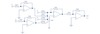
3.A) Identify the particular op-amp circuits used.

From top left corner going down: Non-Inverting Amplifier, Differential Amplifier, and Inverting Summing amplifier.
- B) In the circuit below determine Vout in each case.
i) V1 = 1.00 V; V2 = 2.00V; V3 = 4.00V; V4 = 8.00V

1st Amplifier gain: ((20kΩ + 10kΩ)/10kΩ)=3
2nd Amplifier gain: -100kΩ/20kΩ=-5
3rd Amplifier summing ratios: V_2→-10kΩ/20kΩ=-0.5; V_3→-10kΩ/40kΩ=-0.25; V_4→-10kΩ/80kΩ=-0.125
3rd Amplifier output: -0.5V_2+ -0.25V_3+ -0.125V_4
Actual Math:
3*V_1=3V; -0.5V_2+ -0.25V_3+ -0.125V_4= -3V; -5 (V_b-V_a)= 30V
Vout = -30V*
- B) In the circuit below determine Vout in each case.
ii) V1 = -1.25V; V2 = 5.00V; V3 = 5.00V; V4 = 5.00V
1st Amplifier gain: ((20kΩ + 10kΩ)/10kΩ)=3
2nd Amplifier gain: -100kΩ/20kΩ=-5
3rd Amplifier summing ratios: V_2→-10kΩ/20kΩ=-0.5; V_3→-10kΩ/40kΩ=-0.25; V_4→-10kΩ/80kΩ=-0.125
3rd Amplifier output: -0.5V_2+ -0.25V_3+ -0.125V_4
Actual Math:
3*V_1=-3.75V; -0.5V_2+ -0.25V_3+ -0.125V_4= -4.375V; -5 (V_b-V_a)= -3.125V
Vout = -3.125V
4.a) Using the figure below as a helpful example, design a signal conditioner that will take a -50mV to +50mV output from a thermocouple and convert it into a voltage range of 0 to 5V respectively.

2nd Amplifier gain: -5V/((50mV- -50mV) )=-50; if R_f 10kΩ used,then: 10kΩ/50=200Ω
Offset: -50mV* -50=2.5V; 5V-2.5V=2.5V; 2.5V/(-50)=-50mV
Offset = -50mV
b) Design a signal conditioner that will take an input of -15 to +15V and convert it to a voltage range of 0 to 5V respectively.

2nd Amplifier gain: -5V/((15V- -15V) )=-1/6; if R_f 10kΩ used,then: 10kΩ/(1/6)=60kΩ
Offset: -15V* -1/6=2.5V; 5V-2.5V=2.5V; 2.5V/(-1/6)=-15V
Offset = -15V
c) Design a signal conditioner that will take an input of -15 to +35V and convert it to a voltage range of -2.5 to 2.5V respectively.

2nd Amplifier gain: -5V/((35V- -15V) )=-0.1; if R_f 10kΩ used,then: 10kΩ/0.1=100kΩ
Offset: -35V* -0.1=3.5V; 2.5V-3.5V=-1V; (-1V)/(-0.1)=10V
Offset = 10V
d) Design a signal conditioner that will take a differential (Vb-Va) input of -15 to +15V and convert it to a voltage range of 0 to 5V respectively.

2nd Amplifier gain: -5V/((15V- -15V) )=-1/6; if R_f 10kΩ used,then: 10kΩ/(1/6)=60kΩ
Offset: -15V* -1/6=2.5V; 5V-2.5V=2.5V; 2.5V/(-1/6)=-15V
Offset = -15V
e) Design a signal conditioner that will take a resistance change of 100Ω to 125Ω and convert it to a voltage range of 0 to 5V respectively.

V_a-V_bmax=(125Ω/((125Ω+100Ω) )-10kΩ/((10kΩ+10kΩ) ))*50V_DC=2.78V
V_a-V_bmin=(100Ω/((100Ω+100Ω) )-10kΩ/((10kΩ+10kΩ) ))*50V_DC=0V
Amplifier gain: -5V/((2.78V-0) )=-1.8; if R_f 10kΩ used,then: 10kΩ/1.8=5.56kΩ
Offset: -2.78V* -1.8=5V; 5V-5V=0V; 0V/(-1.8)=0V
Offset = 0V
- Design a current-to-voltage converter that converts a 20mA input signal into a 5V output signal.
R = 5V/20mA = 250 ohm

- Design a voltage-to-current converter that converts a 20V DC input signal into a 20mA current signal.
R = 20V/20mA = 1k ohm

- A) Which op amp circuit is used to connect high output impedance sources with low input impedance loads?
Voltage follower
b) Which op amp circuit could be used as an error detector, subtracting one positive voltage from another?
Differential amplifier
c) Which op amp circuit is the basis for a digital to analog converter?
Summing Amp
- Why do we configure the resistors around an op amp to produce a differential amplifier if the op amp is already a difference amplifying device?
Adding resistors around the opamp allows us to employ feedback and this along with the proper resistor selection allows us to control the gain. i.e. Make it much lower.
- Determine the output of the amplifier.

R_Th=(1/((1/10kΩ)+(1/10kΩ)+(1/10kΩ) ))=3333.33Ω ,∴Individual Gain=1/3
V_a→5V/3+3V/3+1V/3=3V
V_out= ((R_f+R_in)/R_in )*V_in=((20kΩ+10kΩ)/10kΩ)*3V=9V
State, and in two or three sentences each, explain the six functions of the signal conditioner
1) Amplification; increase or decrease the signal level as appropriate. 2) Compensation; adjust for temperature or provide a temperature refence, adjust for the negative effects of environmental variables. 3) Conversion; changes the measured variable from one form to another. 4) Isolation; protection of the measured variables and of the controller. 5) Linearization; takes a non-linear sensor output and converts it to a linear output. 6) Noise Reduction; prevents or remove noise noise from lines using grounding, shielding, twisting of lines, and filtering.
Sketch a typical sample-and-hold circuit. How are there two different time constants in use in its operation?
The sampling time constant comes from the output impedance of A1 and C. The hold time constant comes from the input impedance of A2 and C.

What two characteristics of the op-amp make the voltage follower configuration useful as a buffer on the input of a differential amplifier?
1) A very high input impedance. 2) A low output impedance.
