Questions Flashcards

1
Q

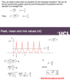
Calculate RMS for this signal

A
2
Q

Calculate 2nd part of the question.

A

If you take the integral of the right-hand cosine you will be left with two sines. The first sine will be equal to sin(4pi +phi) and second sin(phi). The first sine is essentially equal to sin(phi) [since 4pi is just two rotations], thus the whole integral is equal to zero.

3
Q

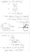
How would you determine the power factor from these two equations for I and V?

And the power dissipated?

A

Find the phase difference between V and I.

Which means subtract phase of I from phase of V.

Since both equations are sinusoidal, A/√(2) can be used to calculate RMS.

4
Q

Calculate iii)

A
5
Q

Determine ii)

what do you need to remember about the period of these sawteeth…

A

That one tooth is one period…

So 20ms relates to one tooth.

6
Q

Determine the power factor.

A
7
Q

State how the emf across an inductor is related to the change in current.

A
8
Q

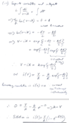
Derive differential equation, then solve and rearrange for i(t).

A
9
Q

Sketch the equation given.

V = 10

R = 4kΩ

L = 280mH

Label any relevant time scales and values.

A

Remember to calculate tau(L/R) and asymptote (V/R)

10
Q

Using the info the plot for i(t), determine the plots for voltage drop across the resistor and inductor.

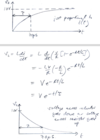
A
11
Q

How would you go about solving this question?

Focus on the second part of the question.

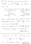
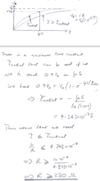
Key sentence: “…at least 0.9V0…”

A

First, you equate 0.9V0 to the rest of the terms.

Solve for taucritical .

It is important to note that in the solutions, the (-)ve in front of tau critical is immediately used to flip the greater than sign.

Lastly, solve for R.
12
Q

What is an important concept to realize when solving these questions?

A

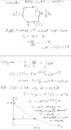
That when the switch is moved to B there no longer is a closed loop with the voltage source, so the current in the loop is going to dissipate.

You apply Kirchoffs 2nd law to the loop formed by the inductor and the resistor.
13
Q

How do you remember current/voltage relationships in capacitors and inductors?

A

using the mnemonic CIVIL,

we know that in a capacitor voltage lags current .

For an inductor, V leads current (or current lags voltage).

Somewhat confusing as L is behind both V and I. Just remember that the C and L represent the capacitor and inductor respectively while the Is and V represent the current/voltage relationship going from left to right.

14
Q

What would be the best way of determining i(t) or v(t)?

A

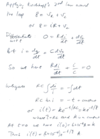
First and foremost, apply Kirchoff’s law around the loop.

Then what you can do is differentiate w.r.t ‘t’.

This will leave dvc /dt which you can rewrite as i/C.

Then solve for i(t)

If they give you a voltage source you should probably be thinking of applying Kirchoff’s 2nd law to start with.
15
Q

What is the solution for this form of differential equation?

A
16
Q

What did you learn from this question?

A
  • That you can relate a 2nd order differential equation of the form ay’’ + y = 0 to y(t) = ksin(ω*t + Ф).
  • You can find ω by plugging general solution into the differential equation.
  • For this LC circuit when finding the particular solution and it has been defined that at t = 0 there is no current flowing, you can safely assume that the phase shift Ф is going to be zero since the charge in an inductor cannot instantaneously change. Similarly, for the capacitor, since it is uncharged at t=0 and the voltage across it cannot instantaneously change it can be assumed that the total voltage in the circuit Vin is equal to the voltage across the inductor VL = 0.
17
Q

Solve iii)

A
18
Q

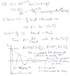
If this is the general solution, the boundary conditions are v(0) = Q0/C and v’(0)=0 and the time period of oscillation T is much shorter than tau, make a rough sketch of vc(t).

A
19
Q

The current system is lightly damped.

Instead of letting it oscillate you wish to optimize the system so that it settles as quickly as possible after changes are made.

If L = 0.1 mH and C = 1µF what resistor R would you need?

A

Realise that for it to be critically damped there should be coincident roots and thus the values in the square root need to equate to each other.

20
Q

What is the unit for bandwidth?

A

rad*s-1

21
Q

Solve ii) given that inductor is 5H and the capacitor is 0.2µF.

A
22
Q

How could you use this circuit as a voltage amplifier? (Hint: look at your answer to ii.) Do you suppose it can give power amplification?

A
23
Q

In the simplest crystal radios an LCR circuit connected to an antenna is used as a resonant detector. It can be tuned to the carrier frequency of different radio stations by using a variable capacitor to adjust the resonant frequency. But why would it be a good idea to omit the resistor altogether, and to try and minimise the resistance of the wire used to wind the inductor coil?

A
24
Q

When you see a circuit that only has parallel components, what do you immediately know?

A

same voltage drop across all componenets.

25
Q

Sketch the magnitude and phase of a parallel LCR.

What kind of filter could this be useful for?

A
26
Q

What would a plot of the magnitude of the voltage across circuit versus frequency look like if you replaced the voltage source by an ideal current source?

A
27
Q

Find general solution and determine constants.

A
28
Q

Determine ii) and iii)

A
29
Q

Derive an expression for the mutual inductance between two concentric circular loops of radii a and b lying in the same plane if b >> a. State any approximations you make. [The magnetic field at the centre of a circular loop of radius r carrying current I is B =μ0I/2πr.]

What did you learn about his question?

A

That you should probably use any equation given…

And that these problems where a small coil is in the same plane of a much larger coil can be solved using the equation of B that determines magnetic field strength at a specific point. Remember, at the centre of the coil, the distance between the point and the magnetic field strength is equal to the radius of the loop.

30
Q

Answer iv)

A
31
Q

The circuit above is essentially a simple transformer, but you probably found its behavior differs from our analysis of transformers where the induced emf was the same at all frequencies and depended on the turns ratio N2/N1. What is different about the above circuit which is causing this difference?

A
32
Q

You want to use a transformer to efficiently couple an 8Ω speaker rated at 20 W to an audio amplifier with an output impedance of 1 kΩ.

Solve i), ii) and ii)

A
33
Q

Why do we step up the voltage to transmit power from power stations? Isn’t the power dissipated in the lines going to go up as V2/R where R is their resistance? Hint: try sketching the complete transmission circuit from power station to home.

A
34
Q

Whats the best way to start solving this BJT DC analysis?

A

Apply Kirchoff’s law to the loop formed by the 5V voltage source.

35
Q

How would you solve this?

What would be the methodology?

A

Its important to realise what you can already solve from the start.

Since, by definition, IC is almost equal to IE, you can calculate RE knowing the current and also it’s voltage drop since the voltage at VE is 1.

Furthermore, you should try to use all the know equations.Such as the relation between VC, VCC, and VRE, or the relation between VB , VCC and resistors 1 &2.

The next value you can calculate is VC through VCC and VRE.

Knowing the Voltage before the collector, VC allows you to determine RL.

IB can be determined through Ic = β*IB.

36
Q

When can you use small signal analysis?

A

You can only use small signal analysis when the AC signals are small enough for the transistor behavior to be linearised.

37
Q

For this balanced delta load configuration what is the current through the loads, if the loads draw 100 W?

A
38
Q

Explain why a 3 phase star configuration has less energy loss than single phase.

A
39
Q

Show how a balanced load delta configuration can give constant power.

A
40
Q

What does the impedance transformation look like?

A
41
Q

Show how the VL can be written in terms of all the impedances.

What do you need to remember?

A

Z1 and Z3 are impedances of primary and secondary winding resistance and flux leakage (represented by an inductor).

Z2 is simply the primary inductance multiplied by the coupling parameter ‘k’.

To find expression for 3VL you need to use potential division between RL and Z3 .

To find expression for Vp you need to use potential division between the parallel combination of Z2 and (Z3 + RL) and impedance Z1 .

Transpose to get the final equation for VL

42
Q

What is an important difference you need to remember between the turns ratio equation and the impedance calculations for impedance transformation?

A

The turns ratio is Ns/Np

The impedance transformation equation is (Np/Ns)2R

So the ratio is flipped, remember that!

43
Q

What’s an important thing you learned from this question?

A

You need to really understand what they’re saying. “The transformer has…a primary winding resistance such that the copper loss in the primary winding is equal to the copper loss in the secondary winding”, what they are saying here is that the power lost in the primary winding due to ohmic losses is the same as the secondary winding.

Also in these questions, if they don’t give you any way of determining the inductances for the windings, you just analyze the power transfer across the transformer.

If you have parameters like the power of a component then you could determine the resistance or current through a component. This was an important part of this question.

44
Q

What are the equation forms and the phasor diagram of a 3 phase generator?

A

These equations are the general forms.

NOTE: Equation for emf should actually be using sine.

45
Q

Specifically, calculate the largest line voltage.

A
46
Q

Show that VL-L = √3 VL-N

A

Important to note that VL-N is equal to the component of VA and VB .

So both can be replaced VL-N and the two components can be added.

47
Q

What do you need to remember about the angle of the line voltages?

What is the full expression of the line voltage?

A

The line voltage makes its own voltage relative to the x-axis, you got to use this.

For delta, the angles are 150, -90 and 30.

|VL-L|*cos(wt + phi)

48
Q

When you have to find the line currents and you’re dividing a sinusoid (cosine) by a phasor, what do you do ?

A

Just do regular phasor division.

So divide the magnitudes, and subtract (add) the angles.

Makes sure you convert to degrees if one is in radians.

49
Q

Go over how you would solve this?

A

Calculate line voltages, remember to use the full expression and that for the angles you take it relative the x-axis.

Next, you can calc the load currents by dividing the line voltages found by the respective impedances.

Equations for line current can be created using Kirchoff’s 1st law.

Using the load currents found the line currents can be calculated using these equations. You subtract using line currents.

Using all the phases obtained creat a phasor diagram

50
Q

How do you solve this question?

A

the key here is that load current was determined by dividing the line voltage (398 V rms) by 50.

Then the line current was determined through the relationship sqrt(3)*load current = line current.

This is because the line current is the vector sum of 2 load currents.

For the star load case: the line voltage is connected across 2 load resistors. What you do is determine the LOAD voltage, by dividing line voltage (398 rms) by sqrt(3). Then you divide this voltage by 50 to get the load current.

For a star load the line currents are the same as the load currents

Heat dissipated is found using (Irms)2R for the 3 resistances.

51
Q

How do line voltage and load voltage relate for star and delta configurations?

Similarly how do line and load current relate for the two.

A

For star:

Line voltage = sqrt(3)*load voltage

line current = load current

For delta:

Line voltage = load voltage

Line current = sqrt(3)*load current

52
Q

Do ii)

A

you need to know the relationships between line current and load current as well as line voltage and load voltage for the two configurations.