Current Electricity Flashcards
current
is a flow of charge and that current is measured in amperes.

charge =
Q
current × time

I x t
describe the use of an ammeter with different ranges
The electric current flowing in a circuit can be measured by connecting an ammeter series
to the circuit. There are different ranges of ammeters as shown below. So when you are
measuring current through a circuit, to measure the current accurately remember to use
appropriate range of ammeter. For example the first ammeter shown below can be used to
measure current of 0 to 1A and another can be used to measure 5 to 30A of current.

electromotive force (e.m.f.)
is measured by the energy dissipated by a source in driving a unit charge around a complete circuit.

The EMF of a power supply (measured in volts, V) is the amount of energy (measured in joules, J) supplied to each coulomb of charge passing through that power supply
e.m.f.

work done/charge

1V
1 J/C
calculate the total e.m.f. where several sources are arranged in series or parallel and discuss how this is used in the design of batteries.
discuss the advantage of making a battery from several equal voltage sources of e.m.f. arranged in parallel.
When two or more batteries are placed in parallel, the voltage in the circuit is the same as each individual battery. That is two, three, four or more 1.5 Volt batteries in parallel will produce a voltage of 1.5 Volts! … When batteries are connected in series, the voltage increases.

Potential differece across a component in a circuit
is given by the work done in the component/charge passed through the component.

Potential Difference & Energy

Resistance
This depends on the resistance of the resistor.
For a fixed potential across a resistor, the greater its resistance the smaller the
current that will flow through it.

Determining Resistance
state Ohm’s Law and discuss the temperature limitation on Ohm’s Law.
Under constant temperature, p.d. is directly proportional to the
current.
This is called Ohm’s law
The apparatus below is a temperature bath which can mantain constant temperatures for experimental purposes.

So in practical circuits we cannot maintain constant temperature. What happens to resistance in conductors when temperature increases?
The resistance of the most of the conductors becomes higher if the temperature of the
conductor increases. As the temperature rises, the metals ions vibrate more and provide
greater resistance to flow the electrons. For example filament lamp, as the current flows
through the metal filament, it gets hotter so its resistance increases. This means the
current varies with voltage is not directly proportional and not give straight line for current-voltage graph.

In semiconductors, increase in temperature has an effect different to conductors.
As temperature increases, the resistor of semiconductors _______.
LDR and thermisters are examples of semi-conductors.
decreases

Bulb vs Fiilament Lamp
Examiner uses the term ‘bulb’ to imply an ohmic resister,
The term ‘Filament lamp’ implies a Non-Ohmic conductor.

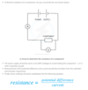
use quantitatively the proportionality between resistance and the length and the cross-sectional area of a wire
The resistance of a wire is proportional to its length
This means that if the length of a wire is doubled, its resistance will double
The resistance of a wire is inversely proportional to its cross-sectional area
This means that is the cross-sectional area of a wire is doubled, its resistance will halve
NOTE:
Cross-sectional area is proportional to the diameter squared.
This means that if the diameter is doubled, the cross-sectional area will quadruple, causing the resistance to drop to a quarter.
calculate the net effect of a number of resistors in series and in parallel.

describe the operation of a light-dependent resistor.

