Ch 5: Handy Circuit Analysis Techniques Flashcards
(27 cards)
Handy Circuit Analysis Techniques and Principles
covered in this chapter
Superposition
Source Transformation
Thévenin Equivalent Circuit
Norton Equivalent Circuit
Maximum Power Transfer Theorem
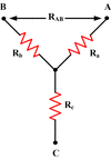
Delta-Wye Equivalents
Linear Circuit:
Definition
A circuit composed entirely of:
- Independent Sources
- Linear Dependent Sources
- Linear Elements
Linear Element:
Definition
A passive element that has a linear voltage-current relationship
Superposition:
Basic Idea
Remove all independent sources.
Then, apply one source at a time, calculating the resulting voltage or current values.
Finally, add the results together.
*Only applies to linear circuits.
Superposition:
Steps
- Turn off all independent sources except one. Find the output voltage or current due to that source
- Repeat for each independent source
- Find the total contribution by summing all the contributions due to the independent sources
Principle of
Superposition
The total response(desired current or voltage) of a Linear Circuit with multiple independent sources can be obtained by summing the responses caused by the separate independent sources.
Superposition:
How to turn off an Independent Current Source
Simply remove the source, replacing it with an open circuit.
Superposition:
How to turn off a Voltage Source
Take out the source, connect the two terminals.
Replaces the Voltage Source with a short circuit.
Practical Current Source
A current source model that more closely matches real world sources.
Represents the internal resistance inherent in a current source by placing a very resistance in parallel with an ideal current source.
Practical Voltage Source
A more accurate model of real voltage sources.
Represents the internal resistance of the source by placing a small resistance in series with an Ideal Voltage Source
Source Transformation:
Basic Idea
Practical Current Sources can be electrically equivalent to Practical Voltage Sources.
Source Transformation:
Equivalency Equations
A Practical Voltage Source has a Voltage Vs, and an internal resistance Rs in series with it.
The equivalent Practical Current Source has a current is and an internal resistance Rp in parallel with it.
For these to be equivalent:
Rs = Rp
vs = Rpis = Rsis
is = vs/Rs
Source Transformation:
Important Points
(8)
- Common goal:
- End up with all current sources or all voltage sources
- Can be used repeatedly to simplify a circuit
- Resistor value stays the same, but is NOT the same resistor. Currents and Voltages associated with the resistor are lost
- If the resistor’s voltage or current controls a dependent source, it should NOT be used in source transformation
- If the resistor’s voltage or current is of interest, it shouldn’t be used in source transformation
- The head of the current source corresponds to the positive terminal of the voltage source
- To transform a voltage source: needs resistor in series
- To transform a current source: needs a resistor in parallel
Source Transformation:
Transforming a Voltage Source
to a Current Source
For a resistor, R, in series with the voltage source, vs,
Replace the voltage source with current source, is,
where is = vs / R
and place the resistor in parallel with it.
Source Transformation:
Transform a Current Source
to a Voltage Source
For a Current Source, is, in parallel with a resistor, R,
replace both with a Voltage Source, vs,
where vs = isR
Place the resistor in series with the voltage source.
Thévenin’s Theorem:
Basic Idea
An arbitrarily complex linear circuit, with two terminals connected to some load,
can be fully represented by a Voltage Source and a Resistor in series.
Called a Thevenin Equivalent Circuit.
- Vth - is the open circuit voltage at the two terminals, and the value of the Voltage Source in the Equivalent Circuit
- Rth - the resistance at the terminals when independent sources are turned off. Also the resistance in the equivalent circuit
Thévenin’s Theorem:
Steps to finding the
Thévenin Equivalent Circuit
- Rearrange the circuit into two networks, A(circuit to be simplified) and B(the load), connected by 2 wires
- Disconnect Network B. The voltage across the open-circuited two terminals is voc
- Turn off every independent source in network A. Leave dependent sources.
- Connect an independent voltage source with value voc in series with network A
- Simplify to the equivalent resistance Rth
- Connect network B back to network A, B is unchanged
Thévenin’s Theorem:
Turning off current sources
Turning off voltage sources
Turn off Current Source:
Replace with Open Circuit
Turn off Voltage Source:
Replace with Short Circuit
Thévenin’s Theorem:
Two cases when finding Rth
No Dependent Sources:
Rth can be found by just turning off sources
Dependent Sources:
Turn off all independent sources, apply an arbitrary source at the terminals
Norton’s Theorem:
Big Idea
A linear two terminal circuit may be replaced with an equivalent circuit containing a resistor, RN and a current source, IN, in parallel
It is similar to Thevenin’s Theorem, and the equivalent resistance is the same.
Norton’s Theorem:
Relationship to Thévenin’s Theorem
The Norton equivalent Current, IN is the ratio of the Thevenin Voltage, Vth and Resistance, Rth
IN = Vth / Rth
If any two variables can be found, both the Thevenin and Norton equivalent circuits can be found.
Norton’s Theorem:
Steps to finding the Equivalent Circuit
Voc = Rth isc
- Rearrange linear circuit into networks A and B, connected by two wires
- Disconnect network B, short terminals of A. Define a current isc as the current through the short
- Turn off independent sources in network A, leave dependent sources alone
- Connect an independent current source with value isc in parallel with the inactive network
- Connect network B back to network A
Maximum Power Transfer Theorem
An independent voltage source in series with resistance Rs,
or an independent current source in parallel with resistance Rs,
or a network with Thevenin equivalent resistance Rs,
Delivers the maximum power to a load resistance, RL, when the Load resistance matches the the source resistance
RL = Rs
Delta Network:
Circuit Diagram


