Ch 2 Fracture Biomechanics Flashcards
Most important mechanical properties of bone (2)
Strength and stiffness
Plot of measured deformation following application of known load?
Load-deformation curve
Regions of the load deformation curve
- Elastic region: measure of the elasticity of a structure. If the object is loaded only through the elastic region of the curve, it will return to its original shape when the load is removed
2: Yield point: the point beyond which the structure will no longer return to its original shape when the load is removed
3: Plastic region: beyond the yield point, the structure deforms to a much greater extent for a given load (the structure is less stiff) than in the elastic region of the curve. - Ultimate failure point: If the load is progressively increased, the structure will fail at some point. This load is the ultimate failure point on the curve

3 parameters for determining strength of bone
(i) the load that the structure can sustain before failing; (ii) the deformation that it can sustain before failing; and (iii) the energy that it can store before failing, known as toughness
What is toughness?
The energy that can be stored before failure
Where on the load deformation curve is the ultimate strength of the structure?
The ultimate failure point
How do you calculate toughness of the structure from the load deformation curve?
Area under the curve
Importance of toughness relative to fracture pathology?
The more energy a bone absorbs before fracture, the greater the comminution and soft tissue damage that develop at the moment of fracture. Greater toughness = greater energy absorption
What mechanical property is conveyed by the steepness of the slope in the elastic region of the load deformation curve
Stiffness; the steeper the slope, the stiffer the structure
Definition of stress
The force per unit area that develops on a plane surface within a structure in response to an externally applied load
4 types of mechanical stress
1) Normal stress is the intensity of the internal force perpendicular to a plane that passes through a point in the body.
2) Tensile stress - positive
3) Compressive stress - negative
4) Shear stress - the intensity of the internal forces parallel to a plane that passes through a point in the body, expressed as force per unit area
Units of stress
PSI or N/m2 (Pa)
Definition of strain
Localised change in dimension in response to an externally applied load
2 basic types of strain
Linear strain and shear strain
Linear strain
Causes a change in the length of the specimen (often expressed as % change in length)
Shear strain
Angular deformation (γ) expressed in radians
Appearance of the stress strain curve
Similar to load deformation; strain plotted on x axis and stress on y
Definition of strength of bone
Determining strength from stress strain curve
Stress at ultimate failure/breaking of the bone
Defined as the ultimate failure stress on the stress strain curve
(Remember STREngth related to STREss)

Definition of stiffness of bone
Determining stiffness from stress strain curve
Stress/Strain
Relationship between stress and strain
Divide the stress in the elastic portion of the curve by the strain at the same time point. Measures resistance to elastic deformation
Youngs modulus
The modulus of elasticity / stress-strain ratio (slope) when testing in tension or compression only
A measure of stiffness; stiffer materials have higher moduli
Higher modulus = high resistance to elastic deformation. Therefore don’t deform much before breaking. Even though ultimate load to failure may be the same, substances with a nigher modulus will break at lower strain ie less deformation ie more ‘brittle’ - bend less before breaking
Shear modulus
The modulus of elasticity when tested under pure shear forces
Mechanical properties of cortical vs cancellous bone
Cortical bone is stiffer but fails at lower ultimate strain (2%) vs cancellous bone (75% ultimate strain); cortical bone is therefore more brittle - sustains less strain before failure Cancellous bone can store more energy prior to failure vs cortical. It is much more ductile - can deform to a greater degree before fracture
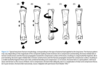
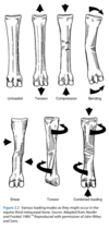
Types of bone loading (5)
Tension, compression, bending, shear, torsion or combinations
BONE IS STRONGER IN COMPRESSION VS TENSION WEAKEST IN TENSION

Anisotropy
Exhibiting different mechanical properties when loaded along different axes
Loading in tension
Equal and opposite traction loads are applied at the ends of a structure, resulting in tensile stresses and strains within the structure Maximal tensile stress occurs on a plane perpendicular to the applied load When subjected to tension, the structure lengthens and narrows, with failure occurring around the osteon by debonding of the cement line and pulling out of osteons
Clinical examples of fractures sustained in tension
Proximal ulna
Some PSB fractures
Patella
Some calcaneal fractures

Clinical features of fractures sustained in tension
Usually transverse, corresponding to plane of maximal tensile stress
Loading in Compression
Equal and opposite compressive loads are applied at the ends of a structure, resulting in compressive stresses and strains within the structure Under compression, the structure shortens and widens, with failure occurring obliquely through osteons.
Clinical features of fractures sustained in compression
Oblique in nature, corresponding to the plane of maximal shear stress (45° to the orientation of the compressive load), since bone as a material is strongest in compression, followed by shear, and is weakest in tension
Clinical ex of fractures sustained in compression
Purely compressive fractures are rare in the horse Y-shaped fractures of the distal humerus and distal femur
Loading in bending
A combination of tension and compression. Tensile stresses act on one side of the neutral axis, and compressive stresses act on the opposite side
Three-point bending
This takes place when three forces act on a structure to produce two equal moments, each being the product of one of the two peripheral forces multiplied by the perpendicular distance from the peripheral force to the middle force. In a homogenous and symmetrical structure subjected to three‐point bending, the structure will fracture through the site of central load application
Fractures sustained in 3-point bending
Ex incl. fractures at the top of a cast, or stepping down a hole Since bone is WEAKEST IN TENSION, fracture occurs on the tension surface of the relevant bone
Typical fracture configuration in 3-point bending
Travels from the tensile surface of the bone to the compressive surface transversely, until shear forces acting on a 45° plane become sufficiently high to result in a butterfly component on the compressive side of the bone
Four-point bending
Occurs when two force couples or four forces (two central and two peripheral) act on a structure to produce two equal moments The region between the two central application points is subjected to a uniform bending moment, and the bone fractures through the weakest point in this central region Not a common clinical fracture type
Loading in torsion
Load causes twisting around an axis, rx in torque production When a structure is subjected to torsion, shear stresses are distributed over the entire structure. As for bending, the magnitude of these stresses is proportional to their distance from the neutral axis (or axis of rotation)
Fracture configuration in torsion
When a bone is loaded in torsion, it first fails in shear with the formation of the initial crack parallel (along the long axis of the cortex) to the neutral axis. A second crack then propagates along the plane of maximal tensile stress, causing a spiral fracture
Combined loading
Most common loading pattern in vivo
Rate dependency of bone
Mechanical behaviour varies with the rate at which it is loaded
Higher rate of loading conveys which property to bone
Increased stiffness at higher loading rates and higher loads to failure, as well as storing higher energy before failure at higher speeds - trauma energy dependent on the second power of the loading rate
Differences in fractures sustained at lower vs higher speeds
At slower speeds more commonly simple fractures with little comminution, the bone and soft tissues remain relatively intact, and there is little or no displacement of the bone fragments. At higher speeds, the bone will absorb more energy before fracture; this stored energy is released, causing more severe comminution and trauma to the surrounding soft tissues
Types of bone failure
Single cycle failure (eg recovery from GA) or repetitive cyclical loading = fatigue fracture
Pathophysiology of repetitive cyclic loading
Each load cycle releases a small amount of strain energy, which can be lost through microcracks along the cement lines. Fatigue load under certain strain rates can cause progressive accumulation of microdamage in cortical bone. When this process continues, the bone may eventually fail through crack propagation Although bone has rather poor fatigue resistance in vitro, it is a living tissue and can undergo repair via remodeling during and after loading. Periosteal callus and new bone formation near the microcrack can arrest crack propagation by reducing the high stresses at the tip of the crack. For the repair process to be effective, a relatively low level of stress must be applied and maintained in the bone. Fatigue loading, for example, is involved in the etiology of dorsal cortical fractures of the third metacarpal bone.
Stress ratio
The ratio of the minimum stress to the maximum stress under cyclic fatigue loading
Stress ratio
Min stress = max compressive stress (as negative) Max stress = max tensile stress
Worst fatigue loading conditions
Stress ratio of -1 An example of this loading condition would involve a fractured tibia with a gap repaired using a single plate. When the horse walks on the limb, the plate is subjected to cycles of compressive and tensile forces; the loading condition would have a stress ratio close to −1
Load to failure and stiffness of the bone are proportional to which geometric property of the bone
Cross-sectional area Larger XSA = stronger, stiffer bone
What is axial stiffness?
In an axial loading test of a structure with an unknown cross‐sectional area (A) and material elastic modulus (E), the slope of the linear portion of the load‐deformation curve is the axial stiffness (AE) of the structure, or the resistance of the structure to axial deformation during loading
What is the area moment of inertia
Biomechanical behaviour of bone when loaded in bending; influenced by XSA and distribution of bone tissue around a neutral axis A larger area moment of inertia results in a stronger and stiffer bone.
How does bone length influence biomechanics behaviour?
The longer the bone, the greater the magnitude of the bending moment caused by the application of a force. Long bones are subjected to high bending moments and therefore must tolerate high tensile and compressive stresses. In a bending test of a specimen with unknown elastic modulus (E) and cross‐sectional area moment of inertia (I), the slope of the linear portion of the load‐deformation curve provides a measure of bending resistance, and this parameter is defined as the bending stiffness or flexural modulus of the structure.
Factors affecting bone biomechanics when loaded in torsion
As for bending - bone XSA and distribution around a neutral axis Termed POLAR MOMENT OF INERTIA What is the polar moment of inertia The effect of XSA and bone distribution around a neutral axis that effects bone biomechanics during torsional loading The larger the polar moment of inertia, the stronger and stiffer the bone. In a torsional test of a specimen with unknown shear modulus (G) and polar area moment of inertia (Jo), the slope of the linear portion of the torque‐rotation curve provides a measure of its torsional resistance or the structural parameter, torsional stiffness.
What is torque?
The load that a cylinder experiences when loaded under torsion
Stress riser definition
Geometric irregularities such as holes, notches, and sharp corners, as well as sudden changes in material properties, may produce high localised stresses in structural members under loading
What is the stress concentration factor
Ratio of true max stress caused by stress riser to the normal stress at that point
What type of loading is the weakening effect of stress risers most prominent in?
Torsional loading
Applications of intra-medullary rods for fixation
Restoration of bony allignment Resumption of normal weight bearing Only suited for young/lightweight animals
Complications of intro-medullary rods
Rod migration Permanent deformation of rod Rod fracture Delayed union Non-union
Properties of IM rods
XSA - overall rigidity incr. w. rod diameter as moment of inertia is proportional to r power4 Rod length Presence of a longitudinal slot Elastic modulus of the material
What is the unsupported length in an IM rod fixation?
Distance between the areas of implant bone contact at the proximal and distal ends of the bone (see fig 2.9)

The unsupported length in bending
For bending loads, the rod is typically loaded in approximately four‐point bending, so the interfragmentary motion is proportional to the square of the unsupported length so a small increase in unsupported length can lead to a larger increase in inter-fragmentary motion
What are locking rods
Mechanism to lock screws to the rod proximally/distally in the bone
Important biomechanics properties for bone plate fixation
Bone properties Plate material Plate geometry Screw-bone interface Number of screws Screw material and tension Plate-bone interface Placement of the plate relative to loading Compression between fragments
What feature of the plate affects its bending stiffness?
Bending stiffness is related to third power of the plate thickness & directly proportional to the elastic modulus of the plate Plate rigidity can be changed more by its thickness than by modulus
How is load transmitted between the plate and bone
Through the bone screws and through friction‐type forces between the plate surface and the bone.
What is plate luting
Use of PMMA or similar to ‘weld’ plate onto bone - increases plate bone contact and frictional forces between the bone and plate
Bending open plate configuration
Plate under bending loads on the compressive surface of the bone
Bending closed plate configuration
Under bending loads on the tensile surface of the bone The plat-bone unit in the BENDING CLOSED position is far stiffer vs bending open
Principles of LCP
Internally positioned ESF device Combines locking screw (LHS) technology with DCU Allows fixation of the screw head to the plate Doesn’t lag the plate to the bone if only LHS are used LHC create fixed angle construct - therefore limited need for plate contouring
Advantages of LCP
Rigidity is maintained even with screw loosening as screws remain tightly fixed to the plate Stable fixation Can use minimally invasively Inherently more stable vs DCP Faster (self tapping) Minimal contouring req Plates can be placed extra-periosteally Sig stronger in vitro 4-point bending Almost twice as strong and stiff in every parameter vs LC-DCP
Disadvantages of LCP
Inability to angle or lag locking screws Significantly increased cost of LCPs and locking screws.
Principles of ESF; 4 features enhancing fracture stiffness
Bone fracture stiffness can be improved with ESF by (i) increasing pin numbers; (ii) increasing pin diameter; (iii) using pins of enhanced material properties (e.g., stainless steel is stiffer than titanium); and (iv) decreasing sidebar separation from the limb
Which is the weakest loading mode for uni or bilateral ESF?
Cranial-Caudal plane
Disadvantages of ESF
>Pin stresses can be high in less rigid systems, causing permanent pin deformation or fracture of the pin. >Even at low loads, systems of minimal stiffness can cause high stresses as pin-bone interfaces, resulting in pressure necrosis that leads to pin‐track infection and loosening
Types of ESF
- a) Unilateral uniplanar - pins/wires connected to a simple bar
- b) Unilateral biplanar - 2 bars at 90 degrees to one another
- Bilateral - 2 connecting bars at 180 degrees to eachother
- Bilateral biplanar - 3 connecting bars - 2 at 180 degrees to one another and the third at 90 degrees to both of these

Equation for stiffness of ESF
Kf = 12MEsI/S3 Kf = axial stiffness M = pins in each bone segment Es = pin modulus I = pin area moment (proportional to the fourth power of pin radius) S = distance from sidebar to the bone
Most important factors affecting stiffness of ESF frame (2)
Distance from sidebar to bone Pin diameter
Most common equine ESF technique
Transfixation pin casting (TFPC)
Method of TFPC
Threaded or non-threaded pins are inserted into the bone above the fractured bone, or the fractured bone above its fractured portion - incorporated into a cast
Benefits of positive profile pins
limit pin migration
Methods to limit pin migration in TFPC
Use positive profile pins Insert pins at 30degree divergence in the frontal plane
Tension surface of the radius
Craniolateral surface Experiences high torsional forces distally Application of a cast makes the caudal surface the tension surface
Tension surface of the tiba
Just lateral of crainial proximal and mid-tibia. Becomes more truly craniolateral distally High torsional forces distally as per radius
Tension surface of MC3
Dorsomedial is the principle tension surface of the forelimb - although highly variable with no true tensile or compressive surfaces
Tension surface of MT3
Dorsolateral
First step in healing of microcracks formed during stress remodelling
Bone resorption induced by osteoclasts
Followed by formation of new osteonal bone by osteoblasts