Ch 17: Wireless Signals and Modulation Flashcards
(32 cards)
Two transmitters are each operating with a transmit power level of 100 mW. When you compare the two absolute power levels, what is the difference in dB?
- 0 dB
- 20 dB
- 100 dB
- You can’t compare power levels in dB.
1.
When the two power levels are the same, the result is 0 dB. As long as you remember the first handy 0 dB fact, you will find exam questions like this easy. If not, you will need to remember that dB = 10log 10 (100 mW / 100 mW) = 10log 10 (1) = 0 dB.
A transmitter is configured to use a power level of 17 mW. One day it is reconfigured to transmit at a new power level of 34 mW. How much has the power level increased, in dB?
- 0 dB
- 2 dB
- 3 dB
- 17 dB
3.
At first glance, 17 mW and 34 mW might seem like odd numbers to work with. Notice that if you double 17, you get 34.
The second handy dB fact says that doubling a power level will increase the dB value by 3.
Transmitter A has a power level of 1 mW, and transmitter B is 100 mW. Compare transmitter B to A using dB, and then identify the correct answer from the following choices.
- 0 dB
- 1 dB
- 10 dB
- 20 dB
- 100 dB
4.
Start with transmitter A’s level of 1 mW and try to figure out some simple operations that can be used to get to transmitter B’s level of 100 mW.
Remember the handy dB facts, which use multiplication by 2 and 10. In this case, 1 mW × 10 = 10mW × 10 = 100 mW. Each multiplication by 10 adds 10 dB, so the end result is 10 + 10 = 20 dB. Notice that transmitter B is being compared to A (the reference level), which is 1 mW. You could also state the end result in dB-milliwatt (dBm).
A transmitter normally uses an absolute power level of 100 mW. Through the course of needed changes, its power level is reduced to 40 mW. What is the power-level change in dB?
- 2.5 dB
- 4 dB
- −4 dB
- −40 dB
3.
This question involves a reduction in the power level, so the dB value must be negative.
Try to find a simple way to start with 100 and get to 40 by multiplying or dividing by 2 or 10. In this case, 100 / 10 = 10; 10 × 2 = 20; 20 × 2 = 40.
Dividing by 10 reduced the dB value by 10 dB; then multiplying by 2 increased the total by +3dB; multiplying again by 2 increased the total by +3 more dB. In other words, dB = −10 + 3 + 3 = −4 dB.
Consider a scenario with a transmitter and a receiver that are separated by some distance. The transmitter uses an absolute power level of 20 dBm. A cable connects the transmitter to its antenna. The receiver also has a cable connecting it to its antenna. Each cable has a loss of 2 dB. The transmitting and receiving antennas each have a gain of 5 dBi. What is the resulting EIRP?
- +20 dBm
- +23 dBm
- +26 dBm
- +34 dBm
- None of these answers are correct.
B.
Remember that the EIRP involves radiated power, and that is calculated using only the transmitter components. The EIRP is the sum of the transmitter power level (+20 dBm), the cable loss (−2 dB), and the antenna gain (+5 dBi). Therefore, the EIRP is +23 dBm.
references:
Effective Isotropically Radiated Power (EIRP) is the maximum amount of power that could be radiated from an antenna, given its antenna gain and the transmitter power of the RF system. EIRP is most commonly given in decibels over isotropic, dBi.
dB: the decibel (dB) is a dimensionless unit, used for quantifying the ratio between two values, such as signal-to-noise ratio.
dBm: (sometimes dBmW or decibel-milliwatts) is unit of level used to indicate that a power ratio is expressed in decibels (dB) with reference to one milliwatt (mW).
dBi: Antenna gain is measured in decibels. It is the ratio between the gain of the antenna compared to the gain of an isotropic antenna. An isotropic antenna is a theoretical antenna which radiates power uniformly in all directions. When we calculate the gain of an antenna and compare it to an isotropic antenna the unit of the gain is dBi (i stands for Isotropic antenna).
A receiver picks up an RF signal from a distant transmitter. Which one of the following represents the best signal quality received? Example values are given in parentheses.
- Low SNR (10 dB), low RSSI (−75 dBm)
- High SNR (30 dB), low RSSI (−75 dBm)
- Low SNR (10 dB), high RSSI (−55 dBm)
- High SNR (30 dB), high RSSI (−55 dBm)
4.
A high SNR is best, where the received signal strength is more elevated above the noise floor.
A 30 dBm SNR separates the signal from the noise more than a 10 dBm SNR does.
Likewise, a higher RSSI value means that the signal strength alone is higher. When RSSI values are presented in dBm, remember that 0 dBm is high, while −100 dBm is very low.
RSSI: Received signal strength indication: In an IEEE 802.11 system, RSSI is the relative received signal strength in a wireless environment, in arbitrary units. RSSI is an indication of the power level being received by the receiving radio after the antenna and possible cable loss. Therefore, the greater the RSSI value, the stronger the signal. Thus, when an RSSI value is represented in a negative form (i.e. 0 to −100), the closer the value is to 100, the closer the signal strength is to 0. The closer to zero it is, the stronger it is.
Which one of the following is the primary cause of free space path loss?
- Spreading
- Absorption
- Humidity levels
- Magnetic field decay
1.
Energy traveling in an electromagnetic wave spreads in three dimensions, weakening the signal strength over a distance.
Which one of the following has the shortest effective range in free space, assuming that the same transmit power level is used for each?
- An 802.11g device
- An 802.11a device
- An 802.11b device
- None of these answers
2.
The 802.11b and g devices operate at 2.4 GHz, which is less affected by free space loss than the 802.11a device, at 5 GHz.
QAM alters which of the following aspects of an RF signal? (Choose two.)
a. Frequency
b. Amplitude
c. Phase
d. Quadrature
2 and 3.
Both 16-QAM and 64-QAM alter the amplitude and phase of a signal.
QAM: Quadrature amplitude modulation is the name of a family of digital modulation methods and a related family of analog modulation methods widely used in modern telecommunications to transmit information. It conveys two analog message signals, or two digital bit streams, by changing (modulating) the amplitudes of two carrier waves, using the amplitude-shift keying (ASK) digital modulation scheme or amplitude modulation (AM) analog modulation scheme. The two carrier waves of the same frequency are out of phase with each other by 90°, a condition known as orthogonality or quadrature. The transmitted signal is created by adding the two carrier waves together. At the receiver, the two waves can be coherently separated (demodulated) because of their orthogonality property. Another key property is that the modulations are low-frequency/low-bandwidth waveforms compared to the carrier frequency, which is known as the narrowband assumption.
Suppose that an 802.11a device moves away from a transmitter. As the signal strength decreases, which one of the following might the device or the transmitter do to improve the signal quality along the way?
- Aggregate more channels
- Use more radio chains
- Switch to a more complex modulation scheme
- Switch to a less complex modulation scheme
4.
By switching to a less-complex modulation scheme, more of the data stream can be repeated to overcome worsening RF conditions. This can be done automatically through DRS.
DRS: An intentional part of the 802.11 standard is Dynamic Rate Switching (DRS). DRS adjusts the data rate in order to reduce retransmissions. If the data rate remains at a high rate when the client is farther from the AP, it will result in so many retransmissions that the actual throughput is greatly reduced.
In Figure 17-16, sources A, B, and C transmit at 4, 8, and 16 mW, respectively.
What is the dB difference between A and C?

In Figure 17-16, sources A, B, and C transmit at 4, 8, and 16 mW, respectively. Source B is double the value of A, so it must be 3 dB greater than A. Likewise, source C is double the value of B, so it must be 3 dB greater than B.
You can also compare sources A and C. To get from A to C, you have to double A, and then double it again. Each time you double a value, just add 3 dB. Therefore, C is 3 dB + 3 dB = 6 dB greater than A.
How many dB difference is there between antennas D and E? Sources D and E have power levels 5 and 200 mW, respectively.

Keep in mind that dB values can be added and subtracted in succession (in case several multiplication and division operations involving 2 and 10 are needed).
Sources D and E have power levels 5 and 200 mW. Try to figure out a way to go from 5 to 200 using only × 2 or × 10 operations. You can double 5 to get 10, then double 10 to get 20, and then multiply by 10 to reach 200 mW. Next, use the dB laws to replace the doubling and × 10 with the dB equivalents. The result is E = D + 3 + 3 + 10 or E = D + 16 dB.
You might also find other ways to reach the same result. For example, you can start with 5 mW, then multiply by 10 to get 50, then double 50 to get 100, then double 100 to reach 200 mW. This time the result is E = D + 10 + 3 + 3 or E = D + 16 dB.

T/F: Cable vendors supply the loss in dB per foot or meter of cable length for each type of cable manufactured.
True.
Because of the physical qualities of the cable that connects an antenna to a transmitter, some signal loss always occurs. Cable vendors supply the loss in dB per foot or meter of cable length for each type of cable manufactured.
What is EIRP?
Once you know the complete combination of transmitter power level, the length of cable, and the antenna gain, you can figure out the actual power level that will be radiated from the antenna. This is known as the effective isotropic radiated power (EIRP), measured in dBm.
EIRP is a very important parameter because it is regulated by government agencies in most countries. In those cases, a system cannot radiate signals higher than a maximum allowable EIRP. To find the EIRP of a system, simply add the transmitter power level to the antenna gain and subtract the cable loss, as illustrated in Figure 17-20.

What is the resulting EIRP of a system with a transmitter configured for a power level of 10 dBm (10 mW). A cable with 5 dB loss connects the transmitter to an antenna with an 8 dBi gain.

Suppose a transmitter is configured for a power level of 10 dBm (10 mW). A cable with 5 dB loss connects the transmitter to an antenna with an 8 dBi gain.
The resulting EIRP of the system is 10 dBm – 5 dB + 8 dBi, or 13 dBm.
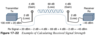
Examine the diagram a calculate the received signal strength in dB.
- The signal begins at 20 dBm at the transmitter
- There is a 2 dB loss for the Tx and Rx cables
- There is a 4dBi gain for both antennas
- The free space loss is -69dB
Note: Free space loss can be calculated as a function of distance and frequency.. For example, you might see a 69 dB Wi-Fi loss over a distance of about 13 to 28 meters.

Figure 17-22 shows some example dB values, as well as the resulting sum of the component parts across the entire signal path.
The signal begins at 20 dBm at the transmitter, has an EIRP value of 22 dBm at the transmitting antenna (20 dBm − 2 dB + 4 dBi), and arrives at the receiver with a level of −45 dBm.
EIRP: The effective isotropic radiated power (EIRP), measured in dBm. To find the EIRP of a system, simply add the transmitter power level to the antenna gain and subtract the cable loss
Fact: Whenever an RF signal is transmitted from an antenna, its amplitude decreases as it travels through free space. Even if there are no obstacles in the path between the transmitter and receiver, the signal strength will weaken. This is known as free space path loss.
T/F: Signal strength falls off quickly near the transmitter but more slowly farther away.
T/F: The loss is a function of time, distance and frequency.
True and False.
- Free space path loss is an exponential function; the signal strength falls off quickly near the transmitter but more slowly farther away.
- The loss is a function of distance and frequency only.
Wireless clients are usually less than 50 meters away from the access point they are using. Does that mean the free space path loss over a short indoor path is negligible?
Not at all.
Even at 1 meter away, the effects of free space cause a loss of around 46 dBm!
T/F: Free space losses are greater with 5GHz than with 2.4GHz.
You should also be aware that the free space path loss is greater in the 5 GHz band than it is in the 2.4 GHz band.
As the frequency increases, so does the loss in dB. This means that 2.4 GHz devices have a greater effective range than 5 GHz devices, assuming an equal transmitted signal strength.
To get a feel for the actual range difference between 2.4 and 5 GHz, a receiver was carried away from the two transmitters until the received signal strength reached −67 dBm. On a 2.4 GHz channel, the range was measured to be 140 feet, whereas at 5 GHz it was reduced to 80 feet. While the free space path loss is the largest contributor to the difference, other factors like antenna size and receiver sensitivity that differ between the 2.4 and 5 GHz radios have some effect, too.
Figure 17-24 shows the range difference, where both transmitters have an equal EIRP. The dashed circles show where the effective range ends, at the point where the signal strength of each transmitter is equal.

What is RSSI?
What are the range of RSSI values?
What is the weakest value? Strongest?
Receivers usually measure a signal’s power level according to the received signal strength indicator (RSSI) scale. The RSSI value is defined in the 802.11 standard as an internal 1-byte relative value ranging from 0 to 255, where 0 is the weakest and 255 is the strongest.
As such, the value has no useful units and the range of RSSI values can vary between one hardware manufacturer and another.
In reality, you will likely see RSSI values that are measured in dBm after they have been converted and scaled to correlate to actual dBm values. Be aware that the results are not standardized across all receiver manufacturers, so an RSSI value can vary from one receiver hardware to another.
What is noise?
All other signals that are received on the same frequency as the one you are trying to receive are simply viewed as noise. The noise level, or the average signal strength of the noise, is called the noise floor.
It is easy to ignore noise as long as the noise floor is well below what you are trying to hear. For example, two people can effectively whisper in a library because there is very little competing noise. Those same two people would become very frustrated if they tried to whisper to each other in a crowded sports arena.
What is SNR? What units is it measured in? Which is better - a higher or a lower value?
Similarly, with an RF signal, the signal strength must be greater than the noise floor by a decent amount so that it can be received and understood correctly.
The difference between the signal and the noise is called the signal-to-noise ratio (SNR), measured in dB.
A higher SNR value is preferred.
Examine the attached diagram and answer the following questions.
- What is the average signal strength?
- What is the noise floor on the LHS of the graph
- What is the SNR?
- On the RHS of the graph the noise floor increase to what? and how does this affect the SNR?
- What is a possible outcome of the noise floor increasing in this graph?

Figure 17-26 shows the received signal strength of a signal compared with the noise floor that is received.
- The signal strength averages around −54 dBm.
- the left side of the graph, the noise floor is −90 dBm.
- The resulting SNR is −54 dBm − (−90) dBm or 36 dB.
- Toward the right side of the graph, the noise floor gradually increases to −65 dBm, reducing the SNR to 11 dB.
- The signal is so close to the noise that it might not be usable.
T/F:
Due to the physical properties of an RF signal, a modulation scheme can alter only phase and amplitude.
False.
Due to the physical properties of an RF signal, a modulation scheme can alter only the following attributes:
- Frequency, but only by varying slightly above or below the carrier frequency
- Phase
- Amplitude


